RS485 Communication Issue with MAX485 – Unable to Connect 28–32 Sensor Nodes

panic mode

Joined Oct 10, 2011
5,469
@Ian0 @Rf300 @MrChips @panic mode I also tested the communication at lower baud rates (19200 and 9600) instead of 115200, but the issue remained the same. Does this indicate that the problem is more likely related to the hardware rather than the baud rate?
that does not tell us anything...

how did you test? what did you change? this problem remains closely related to user.
you were given number of suggestions and all you say is "i tried it again but the issue remained the same". well that does not cut it....
unless we know that that "it" is, ball is your court... if you need help of others, you better tart systematically listing everything you do and how to reproduce your experiments:
* what did you connect and how
* what settings did you use
* what the data is (measurements, not your personal observation that "things do not work")
etc.

Did you examine the signals using an oscilloscope?
not till now
what are you waiting for? why delay inevitable? you still do not know if the issue is hardware of software related (or both). if you want to fund out, you need to devise some test(s). one obvious one is confirming signal shape when 2-3 nodes are connected and when 30+ nodes are connected. you want signal with edges well defined, low noise... unless you look, you will not know what you have.
 
Last edited:

Thread Starter

akash.kumar123

Joined Jul 20, 2026
33
that does not tell us anything. how did you test? what did you change? this problem remains closely related to user. you were given number of suggestions and all you did was say "i tried it again but the issue remained the same". unless we know that that "it" is, ball is your court....


what are you waiting for? why delay inevitable? you still do not know if the issue is hardware of software related (or both). if you want to fund out, you need to devise some test(s). one obvious one is confirming signal shape when 2-3 nodes are connected and when 30+ nodes are connected. you want signal with edges well defined, low noise... unless you look, you will not know what you have.
I wanted to check the software side first before moving to hardware debugging.

I tested the communication at different baud rates (115200, 19200 and 9600), but the issue remained the same.

My next step is to debug the hardware using an oscilloscope. I will compare the RS-485 signal waveforms with a small number of connected sensors and with 30+ sensors connected.
 

drjohsmith

Joined Dec 13, 2021
1,679
I wanted to check the software side first before moving to hardware debugging.

I tested the communication at different baud rates (115200, 19200 and 9600), but the issue remained the same.

My next step is to debug the hardware using an oscilloscope. I will compare the RS-485 signal waveforms with a small number of connected sensors and with 30+ sensors connected.
If you want to check the sw side , you need working hardware !
If hw is not working , your modifying the SW to fix something.
If you must work on SW first, limit your system to three nodes, over short cable.
 

Thread Starter

akash.kumar123

Joined Jul 20, 2026
33
If you want to check the sw side , you need working hardware !
If hw is not working , your modifying the SW to fix something.
If you must work on SW first, limit your system to three nodes, over short cable.
My RS-485 communication system is working reliably with up to 22 sensor nodes. However, I am facing issues when connecting more than 22 nodes, and I am unable to receive data from all 32 sensor nodes.

According to the MAX485 datasheet, the transceiver supports up to 32 unit loads. I want to understand why my system is not communicating reliably with all 32 sensor nodes as expected.
 

MrChips

Joined Oct 2, 2009
35,299
My RS-485 communication system is working reliably with up to 22 sensor nodes. However, I am facing issues when connecting more than 22 nodes, and I am unable to receive data from all 32 sensor nodes.

According to the MAX485 datasheet, the transceiver supports up to 32 unit loads. I want to understand why my system is not communicating reliably with all 32 sensor nodes as expected.
You are repeating yourself. We know the outcome of your network; it is not reliable.
Your problem is user error. Your methodology is GO/NO-GO, i.e. it works or it doesn't work. That gives you no information in order to create a reliable system.

Forget software vs hardware.
Get an oscilloscope and look at the signals, A and B. You can either look at A and B, one at a time. Or you can look at A and B simultaneously using a 2-channel oscilloscope. Document what you observe when you make a single change, not multiple changes at the same time.

Here are things we have told you to do:
1) Remove all TVS diodes
2) Remove all RS-485 bias resistors and install one pair only.
3) Install termination resistors at the start and end of the line.
4) Set the baud to 9600.
5) Remove Q4 and drive DE/RE directly from the MCU.

Don't test if it works or doesn't work. What you want to know is how it affects the A and B signals using the oscilloscope.
If you did all things I listed and it worked for 32 nodes, how would you know which one of the five had the greatest effect?
How would you know if 32 nodes is the limit or you can go to 60 nodes?
 

panic mode

Joined Oct 10, 2011
5,469
you keep repeating same things without sharing anything that confirms correctness of steps taken (if any).
if you want more than 22 nodes working, do not cling to "22 nodes are working" and explore what stops you from talking to 50 or 60 nodes.

you have not confirmed if and what HW repairs are done (TVS removed, biasing resistors removed from all nodes except from master...). you may know it but you never shared it.
you have not confirmed bus topology and if your bus is terminated correctly. in 50 posts thread we all just assume that you know what 485 termination should be but you never proved that. you may know it but you never shared it.
you have not confirmed bus cable type and what makes you sure that you are using twisted pairs in the 8-wire cable, if shielded or not, etc. (there are many Cat 6 types). you may know it but you never shared it.
you have not confirmed how master is polling all the nodes and if there is a software limitation that prevents you from talking to more nodes (like watchdog, buffer size/structure etc). you may know it but you never shared it.
 

panic mode

Joined Oct 10, 2011
5,469
Would it be better to use one twisted pair for RS485 A and another twisted pair for RS485 B, or should A and B be connected through the same twisted pair?
what makes you think that is a good idea? are you planning to replace transceivers from 485 to 488 and make it full duplex? if you have 30+ nodes ready, doing this kind of redesign is late..
 
Last edited:

Rf300

Joined Apr 18, 2025
131
I want to understand why my system is not communicating reliably with all 32 sensor nodes as expected.
The answer is easy:
1. Your enabling circuit is wrong (# 9)
2. 32 bias resistors in parallel (62.5 Ohm effective) are too much. (# 47) One resistor is enough.
3. You might have problems with DC offset (# 43)

Now I see everything has been mentioned by MrChips.

And we need oscilloscope screenshots (DC coupled!) during the receive phase at the sensor at the far end and at the master. Everything else is looking into the crystal ball.
 

drjohsmith

Joined Dec 13, 2021
1,679
My RS-485 communication system is working reliably with up to 22 sensor nodes. However, I am facing issues when connecting more than 22 nodes, and I am unable to receive data from all 32 sensor nodes.

According to the MAX485 datasheet, the transceiver supports up to 32 unit loads. I want to understand why my system is not communicating reliably with all 32 sensor nodes as expected.
But your board is not a unit load.
Remove the resistors on all but the end of the line termination.
Btw. You asked about earth. .
As theses are not transformer isolated , you need to ensure the signal on the inputs is within the common mode range of the receivers earth .
 

0ri0n

Joined Jan 7, 2025
197
According to the MAX485 datasheet, the transceiver supports up to 32 unit loads. I want to understand why my system is not communicating reliably with all 32 sensor nodes as expected.
It doesn't work with the max. allowed number of nodes because of issues with the hardware that have to be corrected first. Missing termination resistors, way to many fail-safe resistors, wrong TVS diode(s). You were alerted a bunch of times about these problems and got suggestions how to fix them. For now consider yourself lucky that it works at all.
 

drjohsmith

Joined Dec 13, 2021
1,679
My RS-485 communication system is working reliably with up to 22 sensor nodes. However, I am facing issues when connecting more than 22 nodes, and I am unable to receive data from all 32 sensor nodes.

According to the MAX485 datasheet, the transceiver supports up to 32 unit loads. I want to understand why my system is not communicating reliably with all 32 sensor nodes as expected.
so,

what is your plan for next few days
 

ronsimpson

Joined Oct 7, 2019
4,896
you should be able to get 32 notes talking without issue
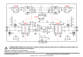
Note the jumpers. J4,5,6,7. The pull-up, and pull-down resistors are only used when the termination resistors are used. If this board was not at the end of a line, the jumpers will be open. (I think this has been said before.)
 
As other people have already said... your SMBJ36CA is the wrong type of TVS diode, because that TVS diode family has high capacitance and is meant to be used on power supply rails. If you already have a PCB, then remove the SMBJ36CA part; in the future when you decide to respin this PCB, change to one of the following SOT23-3 TVS diodes.

The following TVS diodes have low capacitance and meant to be used on data lines, such as RS485 / RS422 / CAN bus. All of the following are dual 24Vrwm TVS diodes in SOT23-3 package, sorted by capacitance. Connect each TVS diode to each RS485 data line, then connect common pin to ground.
* ESD762
* ESDCAN03-2BWY
* TESDA24VB6P02CX
* ESD24VT2BHE3
* CDSOT23-T24CAN
* NUP2105L
 
Last edited:

wraujr

Joined Jun 28, 2022
268
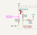
The main problem of the circuit is not the bus termination, it is the driver-enable circuit, consisting of Q4, R25, R28, R29. This circuit enables the driver only while transmitting a "0"-bit. While transmitting a "1"-bit the driver is disabled and the bus level is only driven by the bias resistors. So the bus has more or less the characteristic of an open-collector/drain bus like I2C.

The "DE_RE"-signal should be driven H by an output port of the µC during the whole duration of a transmit telegram and driven L immediately after completion of the telegram.
Good catch. You are 100% correct. This is wrong.
1793745524859.png
The DE/RE are used for half-duplex switching and should be controlled by the uC.
 
Top