RS485 Communication Issue with MAX485 – Unable to Connect 28–32 Sensor Nodes

panic mode

Joined Oct 10, 2011
5,469
in a bus, nodes are connected in parallel. the more nodes you have the worse it gets. those pullup and pulldown resistors are just one example how things that look innocent at first, escalate when numbers grow.
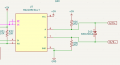
same is with TVS diodes. when things are good, differential pair is operating at some 2.5V difference. at that voltage SMBJ36CA has capacitance of 1000-1100pF. when you add 32 of them in parallel, you get capacitive load of 33nF. that is basically a short circuit for changing signals. just look at the datasheet for signal degradation when the capacitive load is only 50pF. the sharp square edges are no more... which is no surprise for something advertised as "Low-Power, Slew-Rate-Limited".

so either you are to follow the datasheet to the letter (in this case no biasing resistors or TVS) or you need to be careful what you add.

if you are using biasing resistors (some may find it handy for diagnostics if bus is inactive and only tool at hand is DMM), make them really large and added once or twice, not 32 times.
if you are using TVS, use one specifically designed for this application. and be mindful of baud rate. test things slowly, then gradually increase baud rate till you start experiencing problems.
115kbps is a tall order on 100-150m even when using proper bus cable which you are not.
 
Last edited:
Thread Starter

akash.kumar123

Joined Jul 20, 2026
33
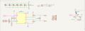
Found this at a company that makes RS485 nodes.
I am using MAX485 transceivers for RS-485 communication between ATmega328PB sensor nodes and an ATmega64A main controller.

When I connect 25 sensor nodes, I fail to receive data from 3–4 sensors. However, with 20–21 nodes, communication works properly. The total cable length for 25 nodes is approximately 78 m using CAT6 cable.

Could this issue be caused by bus loading, termination, bias resistors, baud rate or length of cat6 wire
 

panic mode

Joined Oct 10, 2011
5,469
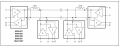
RS485 drivers are meant to handle a 60Ω load, because a 120Ω line terminated at both ends is 60Ω.

You appear to have attempted distributed termination, that does work at low baud rates, with resistors equal to the characteristic impedance divided by twice the number of nodes, but not at 115k baud. 115 k baud needs 120Ω at each end.

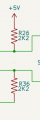
by the way, with 2.2k pull ups on one line and 2.2k pull downs on the other, the driver sees 4.4k, not 2.2k.
those are not terminators, and i doubt he calculated anything.
terminating resistor in his schematics is R23 which can be switched on/off.
in normal setup only two would be used at the end of the bus which is equivalent of 60 ohms.
so lets assume that part if done as intended,
the problem is still that few dozens of R26 are in parallel, as are few dozens of R36 and few dozens of high capacitance TVS.
and the bus is operated at rate that exceeds recommendation for the lengths covered. and the cable is not even proper bus cable. for all we know it is UTP and RJ45 connections are not very good. they are meant for point to point connections, not daisy chaining 32 segments.
so it is not one issue, it is many...

removing all the unnecessary parts (R26, R36, D10) will dramatically change situation and this will likely work fine with all nodes connected and at at 115kbps.

1793196637791.png
 
Last edited:

Thread Starter

akash.kumar123

Joined Jul 20, 2026
33
@MrChips @panic mode @Ian0 @ronsimpson Since each sensor PCB has its own bias resistors and TVS diodes, what changes would you recommend for testing? I have 25 MAX485 nodes connected over 78 m of CAT6, but 3–4 sensors fail to respond. I would appreciate your suggestions on the best test procedure and recommended component values.
 

panic mode

Joined Oct 10, 2011
5,469
Listen to what we are all saying. Remove the bias resistors from all the sensor boards. Remove all the TVS diodes. Apply terminating resistors at the ends only.
Reduce the baud to 9600 and test.
removing all the unnecessary parts (R26, R36, D10) will dramatically change situation and this will likely work fine with all nodes connected and at at 115kbps.
what part of this is not clear?

you have already acknowledged it, just need to act on it:
1793198080096.png
 
Last edited:

ronsimpson

Joined Oct 7, 2019
4,896
I looked in the data sheet and can't find any comments for the two 2.2k resistors. There should be, but it might just be me.
The A and B inputs might output +/-1uA. (from data sheet) This gives me the idea that 2.2meg resistor will pull A high and B low. Certainly, 220k will or 22k. Assuming there are resistors on every board.
I would cut then out for a test, then replace them with 10x or 100x higher a value. On the noteds not the master.
I think 2K2 is fine on the master and 22k to 220k on each node will be fine.
1793205051446.png
If you want a simple way to test this:
Connect the master, a very long wire, and one note. Then solder a 100 ohm resistor across R26 and R36 on the node. This will simulate adding 20 nodes onto the bus. Can you look at the bus with a scope. If adding 100 ohms drops the signal to 1/2 (at the node) then we probably know the answer.
 

wraujr

Joined Jun 28, 2022
268
As others mentioned, terminate with 120ohm at each end of the daisy chain.
Minimize stub length.
Must be daisy-chain topology, no starring or branches.
Remove SMBJ36CA as this is wrong.

1793226215826.png

This is fine, although MAX485 already has floating input protection.
1793226388135.png

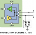
If you must have TVS protection
You must use an asymmetrical dual-TVS array designed specifically for RS-485, such as the industry-standard SM712. It integrates two TVS diodes in a single package with reverse standoff voltagesprecisely matched to the RS-485 spec.
It must be used on every node in your daisy chain
1793226609292.png
 

ZhangSheng

Joined Sep 25, 2026
23
One wiring side that is worth checking separately from bias and termination is how the CAT6 pairs are actually being used, and what happens to the power in the same cable as nodes are added.

1. A and B must be the two conductors of one single twisted pair for the whole run. If A and B are taken from different pairs, or the pair is split at a sensor connector, the cable no longer behaves as a controlled-impedance twisted pair, and problems typically appear only when length and node count grow — which matches your 18-node limit.
2. Keep each sensor connection as a true in-and-out daisy chain with a very short stub to the board. A long spur to a sensor is a branch, not a daisy chain, and it adds reflections as well as capacitance.
3. Because you are also carrying power in the same CAT6 cable, measure the supply voltage and ground at the farthest sensor while all connected nodes are operating, not with the bus idle. As you add nodes, current in those long thin conductors rises, so the far end can lose voltage and its ground can shift relative to the controller. A node that resets or whose transceiver is operating at a lower supply can look like a bus-loading problem.
4. A useful test is to add nodes one at a time and note the exact count at which errors start, then repeat with the sensors powered from a short, separate supply while leaving the data pair unchanged. If the node limit moves, the problem is in the power wiring. If it does not move, the problem is in the data pair, its pair assignment, stubs, or the added capacitance discussed above.

That split test saves swapping parts at random, because the data wiring and the power wiring fail in very similar ways as a chain gets longer.
 

MrChips

Joined Oct 2, 2009
35,299
One wiring side that is worth checking separately from bias and termination is how the CAT6 pairs are actually being used, and what happens to the power in the same cable as nodes are added.

1. A and B must be the two conductors of one single twisted pair for the whole run. If A and B are taken from different pairs, or the pair is split at a sensor connector, the cable no longer behaves as a controlled-impedance twisted pair, and problems typically appear only when length and node count grow — which matches your 18-node limit.
2. Keep each sensor connection as a true in-and-out daisy chain with a very short stub to the board. A long spur to a sensor is a branch, not a daisy chain, and it adds reflections as well as capacitance.
3. Because you are also carrying power in the same CAT6 cable, measure the supply voltage and ground at the farthest sensor while all connected nodes are operating, not with the bus idle. As you add nodes, current in those long thin conductors rises, so the far end can lose voltage and its ground can shift relative to the controller. A node that resets or whose transceiver is operating at a lower supply can look like a bus-loading problem.
4. A useful test is to add nodes one at a time and note the exact count at which errors start, then repeat with the sensors powered from a short, separate supply while leaving the data pair unchanged. If the node limit moves, the problem is in the power wiring. If it does not move, the problem is in the data pair, its pair assignment, stubs, or the added capacitance discussed above.

That split test saves swapping parts at random, because the data wiring and the power wiring fail in very similar ways as a chain gets longer.
All very valid points. You can save a lot of time and effort by examining the RS-485 A and B signals with an oscilloscope. This eliminates the guesswork. You will be able to immediately assess the effects of loading, biasing, termination, capacitance, baud, node count, etc.
 

Rf300

Joined Apr 18, 2025
131
The main problem of the circuit is not the bus termination, it is the driver-enable circuit, consisting of Q4, R25, R28, R29. This circuit enables the driver only while transmitting a "0"-bit. While transmitting a "1"-bit the driver is disabled and the bus level is only driven by the bias resistors. So the bus has more or less the characteristic of an open-collector/drain bus like I2C.

The "DE_RE"-signal should be driven H by an output port of the µC during the whole duration of a transmit telegram and driven L immediately after completion of the telegram.
 

Ian0

Joined Aug 7, 2020
13,317
The main problem of the circuit is not the bus termination, it is the driver-enable circuit, consisting of Q4, R25, R28, R29. This circuit enables the driver only while transmitting a "0"-bit. While transmitting a "1"-bit the driver is disabled and the bus level is only driven by the bias resistors. So the bus has more or less the characteristic of an open-collector/drain bus like I2C.

The "DE_RE"-signal should be driven H by an output port of the µC during the whole duration of a transmit telegram and driven L immediately after completion of the telegram.
If you held TXD high and sent the signal to DE then it would work like a CAN transmitter, and if you had pull DOWNs on A and pull UPs on B, it would work like fault-tolerant CAN with distributed termination.
 

Rf300

Joined Apr 18, 2025
131
If you held TXD high and sent the signal to DE then it would work like a CAN transmitter, and if you had pull DOWNs on A and pull UPs on B, it would work like fault-tolerant CAN with distributed termination.
But with slow signal edges at 0 -> 1 transitions due to high cable capacitance and bias resistors
 

Rf300

Joined Apr 18, 2025
131
No, as already mentioned, it is related to your enable circuit. When transmitting a "1"-level on the bus, your driver has to be enabled. Your circuit doesn't enable the driver to drive the "1"-level actively. Read #32 again.

Edit: typo
 
Last edited:

Thread Starter

akash.kumar123

Joined Jul 20, 2026
33
@Rf300 @Ian0 @MrChips I am using CAT6 cable, which has four twisted pairs. Currently, I am using one pair for +24V, one pair for GND, one pair for RS485 (A and B together in the same pair), and leaving the fourth pair unused. Would it be better to use one twisted pair for RS485 A and another twisted pair for RS485 B, or should A and B be connected through the same twisted pair? Which wiring method is recommended for reliable RS485 communication over longer distances with multiple sensor nodes?
 

MrChips

Joined Oct 2, 2009
35,299
Definitely, A and B must be one and same twisted pair, never on separate pairs.
This is the whole point of having differential signalling on a transmission line.
One of the benefits is better common mode rejection.
 
Top