RS485 Communication Issue with MAX485 – Unable to Connect 28–32 Sensor Nodes

Thread Starter

akash.kumar123

Joined Jul 20, 2026
26
I am using the MAX485 IC for RS485 communication between an ATmega64A main controller and ATmega328PB sensor nodes over CAT6 cable.

Setup:

  • Sensor-to-sensor distance: 3 metres
  • Main controller to first sensor: Variable (3 m, 10 m, 20 m, 30 m, etc.)
  • Topology: Daisy chain
Test Results:

  1. Single RS485 line: Communication works with approximately 18 nodes. After adding more nodes, some sensors stop responding.
  2. Two RS485 lines: Connecting 13 sensors per line allows me to receive data from all 26 sensors.
My target is to achieve reliable communication with 28–32 sensors on a single RS485 network.

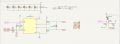
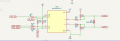
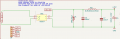
I have attached the main controller and sensor node RS485 circuit diagrams.

Questions:

  • Why am I unable to communicate reliably with more than 18 sensors on a single line?
  • Could termination resistors, bus loading, cable length, or baud rate be the cause?
  • What changes should I make to achieve reliable communication with 28–32 sensors?
Any suggestions or recommendations would be appreciated.

Sensor rs485 circuit.
Image 27-10-26 at 11.07 AM.jpeg


Main controller rs485 circuit
image (13).png
 

Attachments

Since you're using MAX485 transceivers, I'd check the bus loading first. A standard RS485 network supports up to 32 unit loads, including the master, so 32 sensor nodes plus the controller could exceed the limit. However, failing at only 18 nodes makes me suspect signal integrity or biasing as well.

I'd make sure there are only two termination resistors, one at each physical end of the bus, and a single properly designed fail safe bias network. I'd also keep the wiring as a true daisy chain with very short stubs and try reducing the baud rate to see whether reliability improves. If you need 32 sensors plus the master, I'd consider lower unit load transceivers or an RS485 repeater.
 

MrChips

Joined Oct 2, 2009
35,268
There is important information that is missing.

Draw a picture of your physical wiring, showing the length of each line and stub.
Tell us what baud you are using.
Why are you using CAT6 cable instead of a single twisted pair?

Your line biasing and termination is wrong. You only need two bias resistors for the entire network. Remove the diode.
You need two terminating resistors for the entire network, one on each end of the line.

If you wish to split the single network into two, treat it as two separate networks. The controller end has to have two separate RS-485 transceivers. You can drive TXD together and wire-OR the RXD signals.
 

Thread Starter

akash.kumar123

Joined Jul 20, 2026
26
There is important information that is missing.

Draw a picture of your physical wiring, showing the length of each line and stub.
Tell us what baud you are using.
Why are you using CAT6 cable instead of a single twisted pair?

Your line biasing and termination is wrong. You only need two bias resistors for the entire network. Remove the diode.
You need two terminating resistors for the entire network, one on each end of the line.

If you wish to split the single network into two, treat it as two separate networks. The controller end has to have two separate RS-485 transceivers. You can drive TXD together and wire-OR the RXD signals.
I am using a baud rate of 115200 bps for serial communication.

I am using CAT6 cable because it allows me to carry both RS485 communication signals and the power supply to the sensors through a single cable.
 

Attachments

Thread Starter

akash.kumar123

Joined Jul 20, 2026
26
There is important information that is missing.

Draw a picture of your physical wiring, showing the length of each line and stub.
Tell us what baud you are using.
Why are you using CAT6 cable instead of a single twisted pair?

Your line biasing and termination is wrong. You only need two bias resistors for the entire network. Remove the diode.
You need two terminating resistors for the entire network, one on each end of the line.

If you wish to split the single network into two, treat it as two separate networks. The controller end has to have two separate RS-485 transceivers. You can drive TXD together and wire-OR the RXD signals.
And why i have to remove the TVS diode
 

panic mode

Joined Oct 10, 2011
5,417
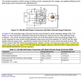
those bulky TVS diodes are tanks, good for protecting power rails. for protection on signal/communication lines there are low capacitance TVS products. common one used on RS485 is SM712 or similar.
here is the basic variant but one does not have to stop there, one can also add TBU on each line so that your circuit disconnects from storm on the bus line.

1793117521920.png
 
Last edited:

Thread Starter

akash.kumar123

Joined Jul 20, 2026
26
How often are you hoping to read them? What protocol have you adopted to prevent data collisions?
The zonal controller polls the sensors for data sequentially at a baud rate of 115200 bps.

We use a request-response communication method, where the controller sends a request to a specific sensor ID and waits for its response before polling the next sensor. This is intended to prevent data collisions on the RS485 bus.
 

Thread Starter

akash.kumar123

Joined Jul 20, 2026
26
I am using the MAX485 IC for RS485 communication between an ATmega64A main controller and ATmega328PB sensor nodes over CAT6 cable.

Setup:

  • Sensor-to-sensor distance: 3 metres
  • Main controller to first sensor: Variable (3 m, 10 m, 20 m, 30 m, etc.)
  • Topology: Daisy chain
Test Results:

  1. Single RS485 line: Communication works with approximately 18 nodes. After adding more nodes, some sensors stop responding.
  2. Two RS485 lines: Connecting 13 sensors per line allows me to receive data from all 26 sensors.
My target is to achieve reliable communication with 28–32 sensors on a single RS485 network.

I have attached the main controller and sensor node RS485 circuit diagrams.

Questions:

  • Why am I unable to communicate reliably with more than 18 sensors on a single line?
  • Could termination resistors, bus loading, cable length, or baud rate be the cause?
  • What changes should I make to achieve reliable communication with 28–32 sensors?
Any suggestions or recommendations would be appreciated.

Sensor rs485 circuit.
Image 27-10-26 at 11.07 AM.jpeg


Main controller rs485 circuit
image (13).png


In my sensor PCB, the 24 V DC+ and DC− from the zonal controller pass through a DB207 bridge rectifier. The RS485 A/B lines are connected, but the GND pin (J9 pin 3) is not connected to the zonal controller's GND. Is this wiring acceptable for reliable RS485 communication over a long CAT6 cable, or should I connect the grounds? Screenshot 2026-10-28 at 11.53.25 AM.png
 
I am using a baud rate of 115200 bps for serial communication.
Do you really need to talk that fast? I know something can't be changed. It seems unreasonable to hit those speeds with long wires and many nodes.
  • Sensor-to-sensor distance: 3 metres
  • Main controller to first sensor: Variable (3 m, 10 m, 20 m, 30 m, etc.)
It would be interesting to know it you can talk to 30 nodes spaced at 30cm. And to know if you can talk to a node at (3 m x 30 = 90m). The questions are to know if 30 nodes at 0 m is the problem, (too many nodes) OR is the problem that wire is too long. Maybe test 4 nodes at 100 m. Probably the problem is (too many X too long X too fast = problem) It would be nice to know if too many or too long was more if the problem.
------------edited---------------
There are RS485 repeaters or boosters that are placed in long lines. I can't remember how they are built but I think you terminate the line and drive it again. I know you don't want to do that.
 
Last edited:
Found this at a company that makes RS485 nodes.
Here’s a general guideline:

Baud Rate (bps)Maximum Recommended Cable Length
9600Up to 1200 meters
19200Up to 600 meters
38400Up to 300 meters
57600Up to 200 meters
115200Up to 100–120 meters
1 MbpsUp to 15–40 meters
Note: Actual performance depends on cable quality, shielding, environment, and impedance matching.
 
I am using the MAX485 IC for RS485 communication between an ATmega64A main controller and ATmega328PB sensor nodes over CAT6 cable.
your statements on test results are contradictory.
what resource did you refer to when adding R26/R36 to your circuit? there is zero mention of this in the MAX datasheet. and if you do have them, why 2k2? that is ridiculously low value. just think what happens when 32 nodes are in the circuit. all of those resistors are in parallel, creating massive and unexpected load for transmitting node. if you are going to use them, make then some 100x larger or better - do not make them part of the board. make them part of terminator (external device) so that only 2 sets will ever be part of the circuit, not 32.
 

Thread Starter

akash.kumar123

Joined Jul 20, 2026
26
your statements on test results are contradictory.
what resource did you refer to when adding R26/R36 to your circuit? there is zero mention of this in the MAX datasheet. and if you do have them, why 2k2? that is ridiculously low value. just think what happens when 32 nodes are in the circuit. all of those resistors are in parallel, creating massive and unexpected load for transmitting node. if you are going to use them, make then some 100x larger or better - do not make them part of the board. make them part of terminator (external device) so that only 2 sets will ever be part of the circuit, not 32.
MAX485 RS-485 network, bias resistors are used to keep the A and B communication lines at a defined voltage when no device is transmitting.
 

MrChips

Joined Oct 2, 2009
35,268
MAX485 RS-485 network, bias resistors are used to keep the A and B communication lines at a defined voltage when no device is transmitting.
Yehbut, 2k2 Ω / 32 = 69 Ω
Your RS-485 drivers cannot handle 69 Ω load.

Listen to what we are all saying. Remove the bias resistors from all the sensor boards. Remove all the TVS diodes. Apply terminating resistors at the ends only.
Reduce the baud to 9600 and test.
 

Ian0

Joined Aug 7, 2020
13,306
Yehbut, 2k2 Ω / 32 = 69 Ω
Your RS-485 drivers cannot handle 69 Ω load.

Listen to what we are all saying. Remove the bias resistors from all the sensor boards. Remove all the TVS diodes. Apply terminating resistors at the ends only.
Reduce the baud to 9600 and test.
RS485 drivers are meant to handle a 60Ω load, because a 120Ω line terminated at both ends is 60Ω.

You appear to have attempted distributed termination, that does work at low baud rates, with resistors equal to the characteristic impedance divided by twice the number of nodes, but not at 115k baud. 115 k baud needs 120Ω at each end.

by the way, with 2.2k pull ups on one line and 2.2k pull downs on the other, the driver sees 4.4k, not 2.2k.
 
Last edited:
Top