RS232 to TTL custom board, no output from MAX232

Thread Starter

Tommaso

Joined Apr 3, 2021
11
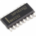
@BobaMosfet Hi, thanks for the help you're giving me, as you can see i'm a noob in making my own circuits. I could have damaged the chip, maybe i'll try soldering another one. No, i'm using non polarized caps, i saw online people using those and tought they could be ok, i don't know i have caps of that size, but i'll try if i find one. I made the pcb layout directly in kicad and there was no error in the nets, then ordered a couple, so i think they're matching. Those max232dr don't have a divot, the only have a white line like this:
1618082272171.png
 

BobaMosfet

Joined Jul 1, 2009
2,211
@BobaMosfet Hi, thanks for the help you're giving me, as you can see i'm a noob in making my own circuits. I could have damaged the chip, maybe i'll try soldering another one. No, i'm using non polarized caps, i saw online people using those and tought they could be ok, i don't know i have caps of that size, but i'll try if i find one. I made the pcb layout directly in kicad and there was no error in the nets, then ordered a couple, so i think they're matching. Those max232dr don't have a divot, the only have a white line like this:
View attachment 235011
I would expect the white bar on end end to tell you which end is the 'top'. |max232 <-- top to the left of "MAX232". You can also look on the bottom and see if there is a pip near a pin, but I'm expecting the white-bar to tell you which end is top.

But to be sure, you MUST look at the datasheet from the OEM that made your chip (MAXIM, TI, etc)- and look at the marking information in the addendum (like this):

1618159514264.png


If you are using the MAX232E, for example, it may behave differently regarding pull-ups and so forth- check the datasheet:

https://www.mouser.com/datasheet/2/256/MAX202E-MAX241E-1292516.pdf

Any time you have CMOS/TTL pins, _YOU_ must add additional pull-ups or pull-downs to keep the IC in the correct state--

1618159314382.png

If you don't, the chip won't operate correctly.

Print your datasheet out. Read it, and write notes on it. Use a highlighter to hilite important sections, Write other notes in a pad. You have to extract what is important to you out of the datasheet, and the only way you can do that is to study it, and reduce the information they give you to only those pieces that are relevant.
 
Looking at minimal details:

Use the +10 and -10 designations on the IC pins
Bypass caps are important with CMOS
Make sure +10, -10 AND 5v are present.

"Typically" unused CMOS inputs need to got to ground or Vcc

The RS232 side uses positive and negative voltages. <-3V and >3V. I'd have to look at datasheets to get details. You should see +-10V.

"TTL RS232" if there is such a thing, is inverted compared to RS232. Whatever that means.

==

Your transistor stuff. You need it to be NPN. You need a base resistor. Anyway design Ib >=10*Ic; Know Vce(sat) at Ic.
Know LED voltage e.g. 2.1 V for red. R(led) <= 5-2.1-0.6; 5V supply, 2.1 led drop, 0.6V Vce Sat

Make sure you have enough current to drive the transistor.

the ULN2003 (7-channel) is a wierd part to understand, but it essentially implements driving relays. There is a pin called common, I belive which is normally connected to the positive relay voltage. It only acts as a return path for the diodes. it's not required when driving LEDs.

==

If I had my druthers, I'd probably use a comparitor and check for >3 and less <-3V; Negative voltage comparitors are probably tricky. The LT6700 would work for positive voltages. Use a 3 pin LED to show all states. e.g. red, green and off.
 

click_here

Joined Sep 22, 2020
548
Double check that your Rx and Tx are the correct way around for the cisco router - There might be an unexpected crossover.

Just put a crossover cable inline and see if it works
 
RS232 used to such a nightmare unless you had one of those "boxes". I think they were like $300.00 in the 80's. With the isolation switch and terminals to add wires you could quickly get something to work.

Later, you could make a custom adapter and be done with it. At work, I never dealt with the RJ50 modular connectors.
The vendors skimped on the true interface or didn't know what they were doing. Decital Equipment and Bell Telephone (103 modems), you plugged them in and it worked. Watch out for current loop devices though.

The Hazeltine 1500 emulation in a z-29 terminal wasn't right.
 
Top