 Facebook
 Google
 GitHub
 Linkedin
RPM sensor
- Thread starter jpickles77
- Start date
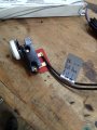
 I hate it when I cant decifer what is being explained. I could really use some basic step by step instructions, I'm very unsure about what I can use to power the sensor, and really cant understand what wires from the wafer cable go where etc....Can I use the power supply I posted? I posted a pic...once I know I have the correct power supply, then I just need someone to say "put this wire with this wire, then connect to this" etc etc. Once again im really sorry but I really don't know allot of the terminology among other things...


| Thread starter | Similar threads | Forum | Replies | Date |
|---|---|---|---|---|
| J | PIR sensor triggering | Sensor Design & Implementation | 4 | |
| E | How to read SPI temperature sensor | Microcontrollers | 2 | |
|
|
Strip Sensor question | Analog & Mixed-Signal Design | 6 | |
| J | Repairing a digital thermometer temp sensor | General Electronics Chat | 4 | |
| S | Mimic PIR Sensor to Achieve AlwaysOn | Sensor Design & Implementation | 21 |


