RL Filter Excercise

ericgibbs

Joined Jan 29, 2010
21,437
hi Andrew,
As a Student, if you agree with the solution, you must have been able to work it out.;)
So please post your calculations so that we can compare.

E
 

Thread Starter

andrew74

Joined Jul 25, 2022
223
hi Andrew,
As a Student, if you agree with the solution, you must have been able to work it out.;)
So please post your calculations so that we can compare.

E
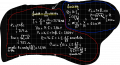
I have calculated in the blue box the power dissipated by the load when the frequency is 0, and the result coincides with the solution.
Assuming that this first part is correct, I am struggling with the same calculation in the red box when working at the cutoff frequency ... I am not able to find the power dissipated by the loadExcercise.png
 

luca290799

Joined Apr 4, 2022
60
Hi Andrew.
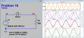
Check these images.
Recalculate and repost.
E

BTW: My figures show a discrepancy with the 2nd posted answer in the link, I will recheck.
@MrAl
Excuse my ignorance ... but I didn't understand how the two photos you attached could be useful to me in calculating the power dissipation at the cutoff frequency :(
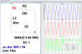
I simulated the circuit on LTSpice and at the cut-off frequency (991 Hz) the resistor dissipates +16mW (or -16mW assuming sinusoidal input) ... this does not coincide with the solution of the exercise.

My initial thought was:
1) \[ P_{total} = R* I^{2} - L*I* \frac{dI}{dt} \]
2) Find: \[ L*I* \frac{dI}{dt} \]
3) \[ [R* I^{2} = [ P_{total} + L*I* \frac{dI}{dt}\] \]


I am not sure about the accuracy of this reasoning :/
 

Papabravo

Joined Feb 24, 2006
22,081
For an ideal inductor there is no real power that is dissipated. This is because the power factor, which is equal to the cosine of the phase angle between the current and voltage waveforms, is cos(90°)=0.

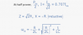
The inductive reactance of the inductor at 991 Hz. is approximately 250Ω. Average power in the load is 32.1 mW.
1658835976635.png
 
Last edited:

luca290799

Joined Apr 4, 2022
60
For an ideal inductor there is no real power that is dissipated. This is because the power factor, which is equal to the cosine of the phase angle between the current and voltage waveforms, is cos(90°)=0.

The inductive reactance of the inductor at 991 Hz. is approximately 250Ω. Average power in the load is 32.1 mW.
View attachment 272233
I thank everyone for the clarification and the simulation of the circuit, which I simulated and found to be the same as yours: average power in the load 32mW.

My difficulty continues to be in the calculation (done on paper, not simulated) of the 32 mW simulated.

When the frequency is 0, we all agree on \[ P = R* I^{2} \]
I would like to see the same calculation but in the case of 991 Hz, resulting in a load power of about 32mW.

Thanks!
 
Top