Rewire Ikea Rolfstrop (2)

Thread Starter

dewieinns

Joined Jan 12, 2024
2
[Originally in reply to this thread, moved here per AAC policy.] —Moderator

Bumping this thread back from the dead as it seems to be about the only thing I can find online that relates to this lamp and people trying to do the same thing I want. I too want to make the lamp turn on as soon as power is applied. It's a $9.99 light fixture and the color temperature matches a bunch of others I have.

I've done some more digging than others here and hopefully, maybe, we can come up with a solution for these.

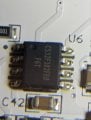
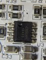
I've attached images for the 3 IC packages. Sorry the images aren't great, the writing on these is REALLY tiny haha

CS32F302FE0 - I can't find anything on this one (while probing this I discovered that if I probed ground and pin1 it activated the capitative switch. Shorting this pin to ground upon startup does nothing unfortunately)
CN3085 - appears to be the battery charger for 3 NiMH batteries
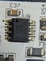
and finally:
The MT7282 is a constant current white LED driver designed for wide input voltage range from 2.5V to 40V system rail.

In looking at the datasheet for it it appears as if there is an adj input so I started probing...

When I run through the different dimmer modes I see the following voltages:
1.49
0.92
0.63

I thought "Hey, if I can just feed the chip one of these voltages when the thing powers up maybe it will come on to that intensity"

No such luck. If I turn the device on with the capacitive switch and I supply a voltage to this (1.49vdc) it DOES come on and stay on at any intensity I ask with that supplied voltage, no smoke has come out yet in my limited testing.

When I look at VIN (Supply Voltage) I'm seeing 7.xx volts with the thing manually turned on. With it off I see ~5vdc...

Before I go poking and prodding too much and do indeed let the smoke out I figure I'd let someone else with more knowledge hopefully chime in.
 

Attachments

Last edited by a moderator:

Thread Starter

dewieinns

Joined Jan 12, 2024
2
Well I found a few more minutes to have another crack at this.

In reading the datasheet again I see "Any voltage above 1.6V will clamp to 100% maximum current." - so I did some more playing around. I found that indeed if I apply 5vdc (readily available) to the chip I can just plug it in and it turns on - I didn't feel great about using 5v for some reason so I looked a bit more and found two resistors (C40, C41) that go to a transistor (U2) and the voltage seems to be ~2.4vdc.

I soldered a mighty-fine jumper between the two, plugged the light in and sure enough it comes on immediately (full intensity)

I'm undecided if full intensity is going to be too bright for my particular application just yet but baby steps. I see where the thing can also accept a pwm signal - I may look at just adding an ESP32 or similar inside the enclosure and doing away with the need to turn it on/off at all. I guess if I do that I could easily fade it on/off as well, maybe even add motion sensing or something... dammit now the gears are turning ;)
 

catlover

Joined May 28, 2025
1
Thank you for this! That cap touch sensor is so annoying.
How did you take apart your Rolfstrop light? I'm trying to pry it apart without damaging the enclosure but its really stuck on there.
 

MisterBill2

Joined Jan 23, 2018
27,159
Given the lack of information at the start of this thread, I am making a guess that the product involved is a touch controlled LED lamp, probably with some irksome peculiarities added as "features." My second guess is that the TS really wants a similar light that is able to switch on and off without the "magic."
The simple approach is to use a regulated power supply of some kind. The regulation does not need to be excellent since the load will not change very much. The supply will need to provide an output voltage with enough current capability to suit the LEDs being powered. It will also need to be adjustable to provide the voltage that delivers the desired brightness.
At that point the TS should be able to control the light simply by switching the mains power on and off.
 

Niklas_R

Joined Nov 2, 2025
1
Well I found a few more minutes to have another crack at this.

In reading the datasheet again I see "Any voltage above 1.6V will clamp to 100% maximum current." - so I did some more playing around. I found that indeed if I apply 5vdc (readily available) to the chip I can just plug it in and it turns on - I didn't feel great about using 5v for some reason so I looked a bit more and found two resistors (C40, C41) that go to a transistor (U2) and the voltage seems to be ~2.4vdc.

I soldered a mighty-fine jumper between the two, plugged the light in and sure enough it comes on immediately (full intensity)

I'm undecided if full intensity is going to be too bright for my particular application just yet but baby steps. I see where the thing can also accept a pwm signal - I may look at just adding an ESP32 or similar inside the enclosure and doing away with the need to turn it on/off at all. I guess if I do that I could easily fade it on/off as well, maybe even add motion sensing or something... dammit now the gears are turning ;)
Can you show is exactly where you installed the jumper cable? :)
 
I added a reply in the original older thread, but will post it here as well. This is my solution to this problem. Hope this helps someone!


There are 3 ICs on the board.

The one closest to the USB connection is a CS32F302, a small MCU from CR Micro (Chineese company), small description available in Chineese here. I have not been able to figure out all of the pin functions, but pin 8 seems to output either a PWM or an analog value, to control the LED driver IC.

The second closest is the LED driver IC. It is a MT7282 from Maxic, small description available here (but the datasheet provided by OP is better). It is the IC driving the current for the LEDs. Pin 2 is called ADJ, and is used to control the dimming of the LEDs, either using an analog singal or PWM. It is connected to the MCU pin 8 via some resistors and capacitors.

The third IC is a battery charging/control IC. When running only on USB this can be ignored.

Since the workings of the MCU is hard to know, as I do not have the code, I will try and bypass that. By measuring the ADJ pin on the LED driver IC for the various dim levels I can see that at the brightest it seems to be at ~1.6V. To acheive that without the MCU interfering, I removed R43 and R45, and pulled the ADJ pin to 5V via a 20k resistor. With 10k resistor (R58) down to GND still present, I get a voltage division and end up with ~1.6V at the ADJ pin. Thus, making the LEDs turn on as soon as I have 5V, i.e. the USB connected.

Resistors to remove (desolder):
remove.png

Addition of pullup via 20k to 5V:

pullup.png
 
Thank you for this! That cap touch sensor is so annoying.
How did you take apart your Rolfstrop light? I'm trying to pry it apart without damaging the enclosure but its really stuck on there.
I used a small flat scredriver and pryed around all the edges, small steps all over. It seems like the top cover is both glued (?) all around but there are also two clasps on each of the ends. But with the glue cracked the small clasps should eventually release if you pry enough.
 

Sigfrid

Joined Apr 13, 2026
1
Thank you Andreas! This was a very good guide! I expanded on the idea and added a ESP32 so I could control it with HomeAssistant through ESPHome. I used a 10k Resistor from a 3,3v GPIO pin on the microcontroller instead of the 20k from 5v and it seems to give me good enough control. I can get it to dim to almost no light output but it flickers on the lowest settings. On brighter settings it is really stable.

I took 5v and gnd from the probe points on the LED side of the board:
PXL_20260418_145716872.MACRO_FOCUS.jpg

and connected gpio 10 to the same spot as Andreas through a 10k resistor:
PXL_20260418_145810337.MACRO_FOCUS.jpg

This is the code I used to control it with ESPhome: The setting for min_power was a trial and error approach, and the rest is to rescale the dimming to give the whole range of available dimming over the 100 % dimming action.

YAML:
light:
  - platform: monochromatic
    output: pwm_out_mapped
    name: "light"
    restore_mode:  RESTORE_DEFAULT_ON


output:
  - platform: ledc
    pin: 10
    id: pwm_out
    min_power: 0.1294
    zero_means_zero: true
  - platform: template
    id: pwm_out_mapped
    type: float
    write_action:
      - if:
          condition:
            lambda: return state > 0;
          then:
            - output.set_level:
                id: pwm_out
                level: !lambda |-
                  float min=id(pwm_out).get_min_power(), max=id(pwm_out).get_max_power();
                  ESP_LOGD("cal", "state: %.2f -> %.2f", state, state * (max - min) + min);
                  return state * (max - min) + min;
          else: # "zero means zero"
            - output.set_level:
                id: pwm_out
                level: 0
 
Top