 Facebook
 Google
 GitHub
 Linkedin
Hi,
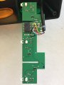
I'm new to this forum and new to electronics as well. I'm trying to fix a USB controlled traffic light which for some reasons can't be recognised anymore by my Windows system. Each of the light could be controlled by a PC but now it is not possible. Power still goes through the device because all lights are lit after connecting to a PC.
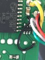
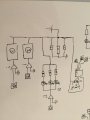
I'm trying to reverse engineer the PCB so I can figure out if I can fix the device or maybe use my raspberry Pi to control the light. I have a sketch of the circuit diagram which I've reverse engineered (probably with errors because of my knowledge). I still can't figure out what two components are and what their functions are to get a better understanding of the diagram. Hopefully some of you know the answers.
I think the micro controller causes current to flow to the triangle (marked "I?") and blocks the flow in some way? Maybe if I know what the component marked "I?" is I can come up with a better explanation. I also can't figure out what the component is next to the micro controller (marked "II ?").
The block marked (2) and (3) are the same parallel circuit as the one with the three LED's (each color of the traffic light uses three LED's).
Any help is welcome.
I'm new to this forum and new to electronics as well. I'm trying to fix a USB controlled traffic light which for some reasons can't be recognised anymore by my Windows system. Each of the light could be controlled by a PC but now it is not possible. Power still goes through the device because all lights are lit after connecting to a PC.
I'm trying to reverse engineer the PCB so I can figure out if I can fix the device or maybe use my raspberry Pi to control the light. I have a sketch of the circuit diagram which I've reverse engineered (probably with errors because of my knowledge). I still can't figure out what two components are and what their functions are to get a better understanding of the diagram. Hopefully some of you know the answers.
I think the micro controller causes current to flow to the triangle (marked "I?") and blocks the flow in some way? Maybe if I know what the component marked "I?" is I can come up with a better explanation. I also can't figure out what the component is next to the micro controller (marked "II ?").
The block marked (2) and (3) are the same parallel circuit as the one with the three LED's (each color of the traffic light uses three LED's).
Any help is welcome.
Attachments
-
 118.1 KB Views: 21
 -
 132.1 KB Views: 24
 -
 120.8 KB Views: 24


