Reverse Biased Diode on Input

Thread Starter

guilhermep

Joined Mar 1, 2018
8
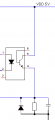
I have attached an image of the circuit that I'm trying to understand. To be 100% honest I don't think I get most of what's going on here.
What I had in mind was that the capacitor was supposed to act as a filter and the resistor to discharge the capacitor, but then there's this reverse biased diode, which I read somewhere that can be used to protect the circuit if the cathode becomes of lower Voltage than the GND it keeps it at -0.7V.

Is my assessment anywhere near the actual truth? If so.. why would you need this kind of protection if the signal is optocoupled?
 

Attachments

WBahn

Joined Mar 31, 2012
32,828
What you need depends on what it is attached to and how it is operated. We need more information before we can provide meaningful feedback.

The diode could provide a few functions. One could be ensuring that the capacitor is never reverse polarized by more than a diode drop. But it could also be to suppress negative going spikes if the incoming signal is AC coupled. Or something else. It depends on what it is attached to and how it is operated.
 

Thread Starter

guilhermep

Joined Mar 1, 2018
8
What you need depends on what it is attached to and how it is operated. We need more information before we can provide meaningful feedback.

The diode could provide a few functions. One could be ensuring that the capacitor is never reverse polarized by more than a diode drop. But it could also be to suppress negative going spikes if the incoming signal is AC coupled. Or something else. It depends on what it is attached to and how it is operated.
Where I wrote "CI input" is literally of the Digital Inputs of a PIC18F4550 so I didn't think it would be necessary. The optocoupler is switching between 5V or nothing. The 5Volts comes from a regulator that is acting on a full bridge rectifier that has something around 10Volts as output.
 

Attachments

Thread Starter

guilhermep

Joined Mar 1, 2018
8
You need to post more than that tiny part of the schematic so we can make sense of the design.

Les.
I was just trying to avoid unecessary work on my part, I'm sorry, but what I have is a lot of messy scribbles, so I put the part of the circuit that was of my interest in a software (tinycad) and printscreened to be more "presentable". Where I wrote "CI input" is really a straight connection to one of the Digital Inputs of a PIC, about the optocouled signal, it's switching 5V on and off accordingly to its command circuit, which I assumed it didn't matter because it's optocoupled. One thing that could matter is that those 5V are originated from a full bridge rectifier that passes through a regulator so it provides 5V.

Sorry if I wasted your time trying to save mine. Thanks in advance.
 

Attachments

LesJones

Joined Jan 8, 2017
4,511
If you are giving us all the relavent information the diode is not required. The capacitor is only requires if the sicnal though the opto coupler is noisy. The resistor is required to pull the input to the microcontroller low when the phototransistor in the opto coupler is not conducting.

Les.
 
Top