Resonant RLC Filters HW HELP!

Thread Starter

AaronR84

Joined Sep 14, 2013
13
Hello to all,

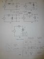
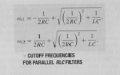
I am trying to calculate the two cutoff frequencies for circuits A through D for the RLC values listed. I know the resonant frequencies are all the same (1E4 rad/s), but I also know the cutoff frequencies are not supposed to all be the same. When I calculate the frequncies they end being the same though. I am using the equations on the page.

I think that of the four circuits A,B,C,D there is one series bandreject filter, one parallel band reject filter, one series bandpass filter, and one parallel bandpass filter. Can anyone tell me if this is right, and also help me out in calculating the cutoff frequencies for each?

Thanks so much in advance for any help! -Aaron
 

shteii01

Joined Feb 19, 2010
4,644
A is called in my textbook: Series RLC bandpass filter.
B is called in my textbook: Series RLC bandreject filter.
C is bandpass filter, there is example in my textbook with that circuit.
D is circuit from C, only the output is taken at the resistor, I think it is bandreject filter.
E, I have no idea.

My textbook: Electric Circuits, 7th Edition, James W. Nilson and Susan A. Riedel.
 
Last edited:

Thread Starter

AaronR84

Joined Sep 14, 2013
13
Thanks, that's what I thought. Circuit 'E' I don't need to worry about. From what my lab instructor told me the cutoff frequencies were not all the same, but I swear they are with all the elements R, L, and C values being the same from circuit to circuit.

Can anyone confirm this?
 

shteii01

Joined Feb 19, 2010
4,644
I can confirm somewhat.

If you look, A and B is the same circuit. What you do is change where you take the output. Same for C and D, the two circuits are the same, you just take output at different places.

So lets take A and B. A is bandpass. Meaning that some low frequencies and high frequencies are being rejected. In A you look at the resistor, that is where you see the frequencies that are allowed to pass. In B you look at the LC combination instead of resistor. So here you can see frequencies that were rejected earlier. The conclusion is that you use same circuit for both filters, the only thing you change is where you look at the output, look at R you get bandpass, look at LC you get bandreject. The cutoff frequencies, the center frequency stay the same.
 

shteii01

Joined Feb 19, 2010
4,644
I must have misunderstood my lab instructor then. Thank you so much for your time!
Do the lab instructions tell you to use different components for each circuit? For each set of circuits?

Like I wrote earlier, A and B are related, C and D are related. But A is not related to C or to D. So the A and B set may use one set of components which will dictate one set of center and cutoff frequencies. C and D may use another set of components, which in turn will have their own set of center and cutoff frequencies.
 

Thread Starter

AaronR84

Joined Sep 14, 2013
13
All four circuits (A-D) have the same R, L, and C values in this case. So A is related to C in that they are both bandpass filters but one is series rlc whole the other is parallel rlc, right?
 

shteii01

Joined Feb 19, 2010
4,644
All four circuits (A-D) have the same R, L, and C values in this case. So A is related to C in that they are both bandpass filters but one is series rlc whole the other is parallel rlc, right?
Ok. I am looking at bandpass.

The serial and parallel bandpass filters have the same center frequency formula.

However, the cutoff frequencies are calculated differently. The formulas are different. So. Even though the two circuits use same components, once you plug the values of the components into the formulas, formulas for series RLC bandbass filter will give you one set of cutoff frequencies, formulas for parallel RLC filter will give you another set of cutoff frequencies.
 

Thread Starter

AaronR84

Joined Sep 14, 2013
13
Do the two formula's for cutoff freq in the picture handwritten at the bottom for the parallel and series rlc look right? They give the same result for cutoff freqs for all four circuits. Also, I realize now I need to post the characteristic transfer functions for each I obtained by voltage division and KCL contain a beta term for bandwidth that all give the same cutoff freqs. The characteristic equations are different but when you plug in these rlc values the result is the same
.
 

WBahn

Joined Mar 31, 2012
33,198
Here's a novel idea. Instead of trying to figure out which magic formula to use, how about analyzing the circuit?

Let's start with Circuit A.

Q1) What is the transfer function, namely the ratio of the output voltage to the input voltage?

To know what question to ask next, I need to get a better feel for the level of math you are comfortable with when working with circuits. Have you done anything with the concept of phasors? How about the use of complex numbers in working with AC circuits?
 

Jony130

Joined Feb 17, 2009
5,600
A is called in my textbook: Series RLC bandpass filter.
B is called in my textbook: Series RLC bandreject filter.
C is bandpass filter, there is example in my textbook with that circuit.
D is circuit from C, only the output is taken at the resistor, I think it is bandreject filter.
E, I have no idea.

My textbook: Electric Circuits, 7th Edition, James W. Nilson and Susan A. Riedel.
There is one simple and intuitive method to establish what type of a filter will are dealing with. All we need to know is that for
F = 0Hz
XL = 0Ω and XC = ∞
And for F = ∞ we have XL = ∞ and XC = 0Ω
And also if we have a parallel tank circuit, Z at resonance frequency is equal to Ztot = ∞
And resonance frequency the impedance of the series tank circuit is at its minimum value (0Ω).

So now let's as try find the type of a filter for "E" diagram.
For the low frequency or DC, the inductors reactance would decrease to zero (acting like a short circuit) and capacitors reactance increase up to infinity causing it to act like a very large resistance (acting like an open circuit).
So Vin = Vout

For the hight frequency the inductors reactance act like a open circuit and capacitors reactance act like a short. So there's no output voltage present at the output.
So this circuit in figure E is a low pass filter.
 

Thread Starter

AaronR84

Joined Sep 14, 2013
13
Thank you jony for the additional insight. WBahn, the transfer functions that I found ultimately answered my question. I had already used all the magic formulas before posting find the meaning behind them.
 

screen1988

Joined Mar 7, 2013
310
So this circuit in figure E is a low pass filter.
Jony, why the resistance is put there? Is it better without that? It seems that it is the resistance of the wire, maybe.

P.S. Well, I have just found the answer, it is related to bandwidth or quality factor of the filter.
 
Last edited:

WBahn

Joined Mar 31, 2012
33,198
Thank you jony for the additional insight. WBahn, the transfer functions that I found ultimately answered my question. I had already used all the magic formulas before posting find the meaning behind them.
I'm reading a bit into the original information you provided, but were you given specific L and C values, or were you given the resonant frequency value, which only really tells you the value of LC? If the latter, then you can change the values of L and C without changing the produce LC and what you will discover is that the product controls the resonant frequency while the ratio controls the Q factor.
 

Thread Starter

AaronR84

Joined Sep 14, 2013
13
OK, I think I have it all figured out now. I have attached all of my calculations and some confirmations I obtained from multisim.

The one thing I don't understand is why the magnitude of Vc in circuit E can be greater than the magnitude of the input voltage. I understand it is a low pass filter. At high frequencies the magnitude of the transfer function is zero, at low frequencies it's one, and at resonant frequency it can be greater than one, if the damping ratio is lower than the resonant frequency.

From what I understand, the magnitude of the transfer functions for circuits A,B,C, and D will never be greater than one at any frequency, so why is the low pass filter different, or am I missing something?
 

WBahn

Joined Mar 31, 2012
33,198
The one thing I don't understand is why the magnitude of Vc in circuit E can be greater than the magnitude of the input voltage. I understand it is a low pass filter. At high frequencies the magnitude of the transfer function is zero, at low frequencies it's one, and at resonant frequency it can be greater than one, if the damping ratio is lower than the resonant frequency.

From what I understand, the magnitude of the transfer functions for circuits A,B,C, and D will never be greater than one at any frequency, so why is the low pass filter different, or am I missing something?
You are contradicting yourself. You say that you don't understand how the magnitude of Vc can be greater than one but then say that the transfer function can be greater than one at the resonant frequency.

What does it mean for a damping ratio to be lower than a frequency? That's like saying as long as my age is less than my height?

It's not that "the low pass filter" is different. It's that in that filter you are taking the voltage across one of the reactive elements and not the other.

Compute the voltage (magnitude and phase) across the capacitor at resonance. Now computer the votlage (magnitude and phase) across the inductor at resonance. Now add the two together to find the voltage across the LC series combination. What does that tell you?
 

Thread Starter

AaronR84

Joined Sep 14, 2013
13
Here is my work.

I guess I can make sense of the magnitude of the cct E's transfer function being greater than one at resonant frequency with the lower damping ratio. I think it's because the capacitor stores voltage and with the input voltage plus the stored voltage leaving the capacitor, the magnitude of the transfer function can exceed one.

So does this make cct E an amplifier at frequencies close to resonance, AND a low pass filter?
 

Attachments

Top