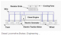
Resistors, 2-pole series dc motor starter

MisterBill2

Joined Jan 23, 2018
27,745
Consider that the same electrical formulas apply to the big stuff as apply to those circuits that fit easily in your hand. Ohms law applies just as well to mega-watts as to milliwatts. The serious difference is the heat generated. Mostly, the way to acomodate heat is to increase the size. So that is why the big testing and control systems would have cages full of cast iron resistor elements. A one ohm hundred amp resistor is going to dissipate ten KILOWATTS of heat, and that takes a lot of mass to handle without melting.
 

MaxHeadRoom

Joined Jul 18, 2013
30,716
Unless this is for purely academic reasons, you have not said why you are particularly making a series field motor?
Usually the whole purpose is due to the very high torque for this type of motor, adding series resistors seems to be defeating the object?
Max.
 

Tonyr1084

Joined Sep 24, 2015
9,744
Megawatage! Wow! In principle I understand something about what you say. Too much for me anyway, I guess. A car sarter motor has 12volts and inrush current even 600amps making modest 7200w. At my level perhaps I try wet wood as resistor, it is a very poor conductor or try this steel wire.
Still I think that in a way or an other I must to get to know how the miracle has done at the practical level with usual car starter motors. I have seen pictures of moving arm going from high to low resistance end. Hard to think that this is only a theoretical picture or that they use very many series/parallel chains. Must be a more simple pactical solution, what are then realworld componets. Nobody knows? Really!
These individual plates were (estimation only) 1/8" thick and about 2 1/2" square. There were dozens of these racks in a dedicated room. ONLY QUALIFIED PERSONS were allowed in during operations. When not operating - it was allowable for QC to enter to inspect. But before one could go in - there was strict protocol to be followed to verify the status of the racks (voltage present or not). Voltages in some cases were 6.8KVAC, and cyclage is a guarded secret. Even I don't know what the Hz was. Only that when they ran the room there were three very large extraction fans in the roof.
 

MisterBill2

Joined Jan 23, 2018
27,745
Certainly stainless steel wire has a greater resistance, but that means that a shorter resistor will be dissipating all of the power. That is not always a benefit, since the heat density takes more effort to keep the wire from doing damage. Spreading the heat over a larger area can be useful.
In addition, stainless wire costs a whole lot more than steel wire such as coat-hangers, like I initially suggested.
 

Thread Starter

wbs

Joined Jul 29, 2020
31
Certainly stainless steel wire has a greater resistance, but that means that a shorter resistor will be dissipating all of the power. That is not always a benefit, since the heat density takes more effort to keep the wire from doing damage. Spreading the heat over a larger area can be useful.
In addition, stainless wire costs a whole lot more than steel wire such as coat-hangers, like I initially suggested.
Stainless steel sounds an interesting and workig solution if resistors needed,only lenght, thickness, resistivity experimentation would be perhaps a small problem.

I am coming to think now a totally different solution:
A "shadow motor" inside my starter motor kind of motor.

I do not use any componets as resistors, thermistors, thyristors, triacs, variacs, rectifiers what ever. I just make a "shadow motor" meaning: I have light winding with 8 gauge wire "on the bottom" of the motor to get high speed when switched on in the beginning developing soon fast spinning and enough back emf. Then I switch on proper heavy switch to start the very heavy copper bar winding, no inrush current any more.

An extra advantage: I can use cordless drill battery too- not shorting the battery switching on only 8 gauge winding which is also there.

btw:In practice to my understanding car starter motors are not ever using any fancy resistor systems to tolerate inrush current , they rely on a balanced design or what ever, do not know. Special resistor systems are only for very large scale motors.
 

MisterBill2

Joined Jan 23, 2018
27,745
Stainless steel sounds an interesting and workig solution if resistors needed,only lenght, thickness, resistivity experimentation would be perhaps a small problem.

I am coming to think now a totally different solution:
A "shadow motor" inside my starter motor kind of motor.

I do not use any componets as resistors, thermistors, thyristors, triacs, variacs, rectifiers what ever. I just make a "shadow motor" meaning: I have light winding with 8 gauge wire "on the bottom" of the motor to get high speed when switched on in the beginning developing soon fast spinning and enough back emf. Then I switch on proper heavy switch to start the very heavy copper bar winding, no inrush current any more.

An extra advantage: I can use cordless drill battery too- not shorting the battery switching on only 8 gauge winding which is also there.

btw:In practice to my understanding car starter motors are not ever using any fancy resistor systems to tolerate inrush current , they rely on a balanced design or what ever, do not know. Special resistor systems are only for very large scale motors.
An engine starter motor is designed for that purpose only. It needs to deliver all of it's torque immediately, before it gets up to speed. Because the application is well understood, that is possible to do.
Many other types of motors also need to start up under load also.

A motor with 8 gage windings will still draw a very large current and is not suitable for being powered by a cordless drill sized battery . In fact, #8 wire is about the size of wire in some smaller automotive application starter motors.

I suggest that the TS read and understand a wire size versus current rating data table intended for motor windings before continuing developing these ideas. The greater insight will certainly be useful.
 

Thread Starter

wbs

Joined Jul 29, 2020
31
An engine starter motor is designed for that purpose only. It needs to deliver all of it's torque immediately, before it gets up to speed. Because the application is well understood, that is possible to do.
Many other types of motors also need to start up under load also.

A motor with 8 gage windings will still draw a very large current and is not suitable for being powered by a cordless drill sized battery . In fact, #8 wire is about the size of wire in some smaller automotive application starter motors.

I suggest that the TS read and understand a wire size versus current rating data table intended for motor windings before continuing developing these ideas. The greater insight will certainly be useful.

Am I all wrong that if I say :
Cordless drill:
-typical voltage 18.5v
-normally ability to output 10 amperes (at least ) not shorting
and

Calculation:
- voltage 18.5
-amperes 10
-wire lenght 20 meters
-maximum voltage drop 4% then
-MINIMUM wire to handle situation continiously not burning
is 9.6 mm2 near 8.4 mm2 (8 gauge)
wattage loss then heating wire 7.4 w

Othervise you are right, I should learn (maybe still better to cancel this kind project).
 

MisterBill2

Joined Jan 23, 2018
27,745
Am I all wrong that if I say :
Cordless drill:
-typical voltage 18.5v
-normally ability to output 10 amperes (at least ) not shorting
and

Calculation:
- voltage 18.5
-amperes 10
-wire lenght 20 meters
-maximum voltage drop 4% then
-MINIMUM wire to handle situation continiously not burning
is 9.6 mm2 near 8.4 mm2 (8 gauge)
wattage loss then heating wire 7.4 w

Othervise you are right, I should learn (maybe still better to cancel this kind project).
First, the starting current in a cordless drill motor is only for much less than a second, because the motor almost immediately reaches full speed. In addition, a cordless drill does not run for long periods of time, and so heat buildup is less. So the considerations for continuous operation are not really applicable.
None of the battery powered cordless tools that I have opened had #10 wire, nothing larger than #14 in the very most powerful ones.
The starting inrush is a very short part of almost all motor applications, and most motors will not last very long if they are kept in the starting mode. Some motors even have a specification as to the maximum number of starts per hour. This is because of the extra heating during the starting period.
The main exception is servomotors, which is a totally separate category, not like other motors.
 

shortbus

Joined Sep 30, 2009
10,049
I suggest that the TS read and understand a wire size versus current rating data table intended for motor windings before continuing developing these ideas. The greater insight will certainly be useful.

I challenge you to even find that information! As someone who has a motor project on the back burner, and has asked both here and at ETO, and has contacted(Emailed) some of the wire producers, the amperage rating when it comes to motor winding is not available. There are amperage charts for other uses, but motors don't follow them. Motors are wound with a much smaller diameter wire than what is used to supply the amperage they need when in use.
 

MisterBill2

Joined Jan 23, 2018
27,745
I challenge you to even find that information! As someone who has a motor project on the back burner, and has asked both here and at ETO, and has contacted(Emailed) some of the wire producers, the amperage rating when it comes to motor winding is not available. There are amperage charts for other uses, but motors don't follow them. Motors are wound with a much smaller diameter wire than what is used to supply the amperage they need when in use.
The textbook was mostly about transformers but there were chapters on electric motors as well. It was an engineering textbook from my father's college classes, and so it was not a current textbook. Certainly it would not be found in the average neighborhood library. It would probably be in the reference section of the library at an older engineering college.
But since motors and transformers are still being designed today the information must still be available.
 

MaxHeadRoom

Joined Jul 18, 2013
30,716
One of the 'Bible's on motors and motor rewinding is Electric Motor Repair by Robert Rosenberg, first published 1946.
I still have my copy and still relevant today.
I would hazard a guess that motor winding gauges have evolved empirically from the various manuf production experiences.
Max.
 

shortbus

Joined Sep 30, 2009
10,049
Max, I also have that one but a newer edition. And that was the answer the wire company gave, that motor makers experimented until they found the smallest gauge that would hold up. I don't have the money for that.:)
 
Top