Facebook
 Google
 GitHub
 Linkedin
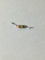
What is the resistor value having color code (5 band).
Orange-orange-gold-gold-green.
Orange-orange-gold-gold-green.
| Thread starter | Similar threads | Forum | Replies | Date |
|---|---|---|---|---|
|
|
L.E.D protection resistor value | General Electronics Chat | 34 | |
| T | What value is this resistor ? | General Electronics Chat | 24 | |
| A | Help finding the value of the SMD capacitor/resistor | Technical Repair | 2 | |
| E | Resistor Value Calculator | Analog & Mixed-Signal Design | 14 | |
| R | Resistor value for polarity protection diode | General Electronics Chat | 5 |