 Facebook
 Google
 GitHub
 Linkedin
Hi all,
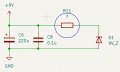
I've just designed a PCB for a project I'm working on and noticed that on some designs there's a resistor in series with the polarity protection diode, I'm guessing to protect it in case the diode breaks down and the current starts to flow through it to ground. But how do I calculate the value of this component? The diode is in parallel with the supply accompanied by some smoothing caps as you can see in the image.
Thanks
Attachments
-
 73.1 KB Views: 20


