Facebook
 Google
 GitHub
 Linkedin
I've built a small electronic dummy load. From the EEVBlog site - turned out to be a pretty interesting project....
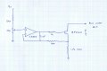
It is a mosfet that is driven by an op-amp keeping the voltage across a load resistor between mosfet source and ground at a set voltage. It is explained really well in the short video if anyone is interested....
My load resistor is 1Ω (10x10Ω in parallel, each metal film 1W).
I had it set to 2A - so the power dissipated is 4W in the 10W resistor bank. With a thermocouple I measured the temp of the resistors around 150°C (300°F). Seems high?? What sort of temp would the average resistor tolerate??
I'm planning a Mk 2 version with a 10x10Ω or 12x12Ω bank in 5W wire wound resistors, hopefully to handle 5A or so.... might be able to use the enclosure to bake cookies!")
Lee
It is a mosfet that is driven by an op-amp keeping the voltage across a load resistor between mosfet source and ground at a set voltage. It is explained really well in the short video if anyone is interested....
My load resistor is 1Ω (10x10Ω in parallel, each metal film 1W).
I had it set to 2A - so the power dissipated is 4W in the 10W resistor bank. With a thermocouple I measured the temp of the resistors around 150°C (300°F). Seems high?? What sort of temp would the average resistor tolerate??
I'm planning a Mk 2 version with a 10x10Ω or 12x12Ω bank in 5W wire wound resistors, hopefully to handle 5A or so.... might be able to use the enclosure to bake cookies!
Lee