Resistor identification clarification

Thread Starter

Mike Baker

Joined Aug 31, 2017
148
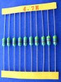
According to the chart (unless im reading it wrong) the below resistor should be 4.7K?

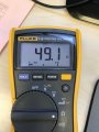
But when i test with my multi meter its more like 47 Ohms......

Am i missing something?

Thanks
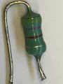
IMG_4079.JPG
IMG_4080.JPG
 

BobaMosfet

Joined Jul 1, 2009
2,211
I'm with MrChips on this- it's either mismarked, or an axial inductor (based on body color).... I tried to mentally _see_ that 3rd band as black and couldn't do it. I could see it as red, as brown... but not black, so...
 

Thread Starter

Mike Baker

Joined Aug 31, 2017
148
I'm with MrChips on this- it's either mismarked, or an axial inductor (based on body color).... I tried to mentally _see_ that 3rd band as black and couldn't do it. I could see it as red, as brown... but not black, so...
Its definitely red....

Whats an axial inductor???
 

GopherT

Joined Nov 23, 2012
8,009
Is it old or in a harsh environment? The top lead looks quite pitted. Unless that was your tool marks from pulling it off of the board.
 

Tonyr1084

Joined Sep 24, 2015
9,744
Don't know about anyone else, but I see Yellow, Purple, Black (470) That makes a 47 ohm resistor in my mind. 10% means it could be anywhere from 42.3 ohms to 51.7 ohms.

Inductor? My guess is - no. Not an inductor. I have seen wire wound resistors, and when they're wrapped in one direction only then they act like inductors, where as when they're wrapped in both directions the inductance cancel's out each other.

Wire wound resistors are typically longer, and if I'm not mistaken, they're lower resistance than 47 ohms. But I suppose you could have a 47 ohm wire wound. Or maybe it's an inductor. Without being able to put my hands on it - can't tell.

As for the third color band, I see back. But I have a hard time with red and green. Red/Green deficient. And here, I've made a living in electronics inspection. That's why I LOVE numbered resistors. But I see black. Not red.

[edit] OK, now I'm looking at this on a different computer monitor. Now it looks burgundy red. But I'm still going with black.
 
Last edited:

Thread Starter

Mike Baker

Joined Aug 31, 2017
148
Don't know about anyone else, but I see Yellow, Purple, Black (470) That makes a 47 ohm resistor in my mind. 10% means it could be anywhere from 42.3 ohms to 51.7 ohms.

Inductor? My guess is - no. Not an inductor. I have seen wire wound resistors, and when they're wrapped in one direction only then they act like inductors, where as when they're wrapped in both directions the inductance cancel's out each other.

Wire wound resistors are typically longer, and if I'm not mistaken, they're lower resistance than 47 ohms. But I suppose you could have a 47 ohm wire wound. Or maybe it's an inductor. Without being able to put my hands on it - can't tell.

As for the third color band, I see back. But I have a hard time with red and green. Red/Green deficient. And here, I've made a living in electronics inspection. That's why I LOVE numbered resistors. But I see black. Not red.
It’s 100% red :)
 

Tonyr1084

Joined Sep 24, 2015
9,744
Look at my edit. Different screen, I see dark dark red.

Someone said it's designated as L2. Well, I don't see any boards in any of the pictures so - - - .
 

WBahn

Joined Mar 31, 2012
32,801
What’s an LR?
It's just a simple circuit with an inductor (L) in series with a resistor (R). When a step voltage is applied (a voltage source turned on), the current rises from zero to its final value exponentially with what is known as a "time constant". For and LR circuit the time constant is L/R. Since you have measured the DC resistance to be about 50 Ω, if that's the R then if it is a 4.7 mH inductor the time constant would be about 0.1 ms. So if you could hook that up to a signal generator producing a square wave at something like 1 kHz (which can be done with a 555 timer pretty easily), then if you could look at the current in the circuit (using a small current-sensing) resistor on an oscilloscope you could determine the time constant and see if it is consistent with it being a 4.7 mH inductor.

Now, I suspect you don't have the one key piece of equipment you would need -- the scope. There are other ways to get an estimate of the answer without it, but they are probably more hassle than they are worth for you.
 
Top