Resistor for RGB LEDs in parallel

Thread Starter

zoom

Joined Jul 11, 2014
29
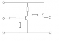
I have 9 common cathode RGB LEDs. I want to connect them in parallel and control R, G an B channels of all the LEDs. To do so I am planning to use 3 transistors. (So, LEDs won't be individually addressed)

Each channel of LED requires 20mA so for 9 of them I need 180mA.

At first I was planning to attach individual resistor for each LEDs' each channel. But that makes too much resistor (3*9 = 27). I tried to find a better solution but couldn't think of any way out.

Any better design suggestions on that ?

Thank you.
 

Thread Starter

zoom

Joined Jul 11, 2014
29
Now that you have worked out how to do a saturated switch, you can do 2 in a row.
Start with this idea and see what you can do.
Thanks for the answer.
However, somehow I couldn't find any useful information about this double inverter design. How does it work and substitute my design ?
 

#12

Joined Nov 30, 2010
18,224
If each transistor can operate as if it had a gain of 10, then to drive 180 ma for 9 LEDs would need about 1.8 ma if you start with this circuit. If you have 18 ma available in the first place, you don't need this circuit at all.
 

Alec_t

Joined Sep 17, 2013
14,330
Connecting LEDs in parallel is not generally recommended, since slight differences in their Vf can result in big differences in their currents. That in turn means some LEDs will hog the current, their life will be shortened, and brightness across the group will be uneven. On the other hand, you might strike lucky and have closely matched Vfs ;).
 

Thread Starter

zoom

Joined Jul 11, 2014
29
If each transistor can operate as if it had a gain of 10, then to drive 180 ma for 9 LEDs would need about 1.8 ma if you start with this circuit. If you have 18 ma available in the first place, you don't need this circuit at all.
I have 5V 40mA at most from arduino output for each transistor. I just want to reduce the number of current limiting resistors used.
 
Last edited:

Thread Starter

zoom

Joined Jul 11, 2014
29
Connecting LEDs in parallel is not generally recommended, since slight differences in their Vf can result in big differences in their currents. That in turn means some LEDs will hog the current, their life will be shortened, and brightness across the group will be uneven. On the other hand, you might strike lucky and have closely matched Vfs ;).
But common cathode RGB LEDs can only be connected in parallel, if I'm not mistaken.
But if I consider the possible change in the Vf and pick the current limiting resistors accordingly for a lower required curren, let's say, 15mA, this might work. Yet, their brightness might not match as you suggested.

So, what is the solution for this ? And my very first question still holds :) How can I reduce the number of resistors used for current limiting purpose. 27 sounds like there is a bad design going on.
 

#12

Joined Nov 30, 2010
18,224
Alec seems to be assuming that you will not use a resistor for each LED. If you only have 5 volts to start with, you can not afford the voltage requirement to put LEDs in series, so the penalty is a resistor for each and every LED.
 
Last edited:

#12

Joined Nov 30, 2010
18,224
You are going to end up with something like this, except you have to fill in the other LEDs because I'm too lazy to do the drawing right.
 

Attachments

Thread Starter

zoom

Joined Jul 11, 2014
29
Alec seems to be assuming that you will not use a resistor for each LED. If you only have 5 volts to start with, you can not afford the voltage requirement to put LEDs in series, so the penalty is a resistor for each and every LED.
Let me clarify that the base voltage for the transistor is 5 volts. I have an adapter providing 9Volts 1Amp. So, LEDs will be connected to 9Volts power supply. Besides, common cathode LEDs cannot be connected in series. 9 volts is anyways less than the voltage required for 9 LEDs in series.

So, apparently I'm bound to use resistors for each and every LED.
 
Top