Resistor and linear regulator in series

Thread Starter

mike_the_begginer

Joined Dec 7, 2019
132
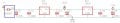
Hello. I have a 20 V dc power supply and a second power supply which has 2 linear regulators, L7812 and L7805 in cascade.
I installed the L7812 and L7805 onto a heat sink but the heat sink is a little bit small and it heats up to about 47 C. I know that in this moment it should be ok, but if the temperature in my room will rise to lets say about 30 C then I don't know if it will be any good.
I already made the PCB (before I saw this problem), and I found that the single solution is to install a resistor in series with D1, between the K of D1 and the + terminal of the capacitors. I made some calculations and tests, and it seems that a 33 R resistor will be ok.
Also, I cannot install a better heat sink (a larger one) because the enclosure for this project is too small.

Are there any better ideas to reduce the voltage on the input of 7812 ?
 

Attachments

DickCappels

Joined Aug 21, 2008
10,152
The best solution depends on what kind of performance your project needs, how much it can cost, and the environment.

If the load does not vary much then there should be no problem putting a resistor in series with the 12V regulator. What would probably give the most robust performance would be, instead of a resistor in series with the 12V regulator is to precede it with a 15 volt pre-regulator providing that drop-out voltage doesn't become an issue.

The overall objective is to spread out the heat over a larger surface by spreading the heat over more components, as opposed to over a larger single heatsink, because that is apparently a problem.

The other direction is to use a switching pre-regulator which would not dissipate much compared to a linear pre-regulator. Just do a good job of filtering out the switching glitches because those analog regulators aren't able to do that well at such high frequencies.

By the way, for small changes in temperatures like those at which silicon is run, the temperature rise of a heatsink will track temperature rises of the ambient air. If the air temperature increases by 10° the heatsink temperature will increase by 10°.
 

Thread Starter

mike_the_begginer

Joined Dec 7, 2019
132
I prefer to use the resistor in series with 1N4007 diode (because I can't get right now the LM2596). The PCB is already done, the components are soldered on the board.
For the tests I used a 20V power supply, but for everyday use I would like to use a 24V power supply - which sometimes (when loaded) it goes to about 21-22V - , so I think that using a 47R / 2W resistor should be better. The current through 7812, measured with multi meter, is about 0.12A.
I measured the power supply, and it was about 24V, at the input of 7812 (after the diode D1 and 47R resistor) the voltage was about 18-19V.
The 24V power supply is a 19V transformer which has a rectifier bridge (8A) and 3x 4700uF / 35V filter capacitors.

Are there any tests that I should make in order to check if the circuit is working correctly ? (other that to check if the heat sink is not heating up as much).
 

MrAl

Joined Jun 17, 2014
11,389
Hi,

One thing you should realize right off. When you use a linear method for stepping down a voltage it will always dissipate the same amount of heat no matter what you use to step it down with. The only thing you can change is the local surface temperatures.
So if you use one regulator with one heat sink, two regulators with two heatsinks, or one or two regulatoss with a series resistor you will always have to dissipate the same power as heat.
For example, a 24v source with 12v regulator with the 12v regulator putting out 1 amp. The 12v regulator has to drop 12v at 1 amp and that is 12 watts. Now add a series resistor of 10 ohms in series with the regulator. The regulator now dissipates 2 watts but the resistor dissipates 10 watts, so we still have a total of 12 watts of power being dissipated as heat. There is no way around it unless you can rig up the 10 ohm resistor to hang outside the 'room' so that the heat from that is dissipated outside. Then you only have 2 watts to dissipate inside.

The right way to do this though is to use a buck regulator. A buck regulator provides a true power conversion where it would 'convert' 24v to 12v and in doing so does not dissipate as much power as resistors or another regulator would. You may only see 2 watts dissipation in the buck which is a lot better than 12 watts, and you dont waste all the energy either. If it happens to be a battery source, the battery will keep the load running for almost twice as long too.

So in the end the best bet is to use a switching regulator which for a step down voltage is called a buck regulator or simply a step down switching regulator. They are available all over web for low cost.
There are many people here who would be happy to help you find one for the mere asking :)
 

Bordodynov

Joined May 20, 2015
3,177
You don't need any resistor. I don't know what chip design you're using. But heating to 70 degrees Celsius is acceptable. That means your circuitry will be reliable at 48 degrees. That is if your stabilizer chips have a temperature range of 0 -70 degrees. If you have an industrial design, you can increase the overheat by another 15 degrees.
 

MrAl

Joined Jun 17, 2014
11,389
You don't need any resistor. I don't know what chip design you're using. But heating to 70 degrees Celsius is acceptable. That means your circuitry will be reliable at 48 degrees. That is if your stabilizer chips have a temperature range of 0 -70 degrees. If you have an industrial design, you can increase the overheat by another 15 degrees.
Yeah but it is not the temperature he is complaining about it is the heat energy itself. It acts like a mini room heater. Ive seen this happen with high piwer CPUs in computer systems, some 200 warrs or higher.
 

Thread Starter

mike_the_begginer

Joined Dec 7, 2019
132
It is acceptable if I install a little fan on the case to pull out the hot air ? And of course, I will drill some holes on the other side of the case.
Does the power supply for the fan needs to be separate or I can use the same 24 V dc output and then use a 24 V fan or use a little step down converter and a 12V fan ?
 

Papabravo

Joined Feb 24, 2006
21,159
People toss PCBs and start over all the time when they realize that a mistake has been made. It's not the end of the world after all.
 

Deleted member 115935

Joined Dec 31, 1969
0
Laws of the land, your dropping a voltage , at a current, then the power dissipated is V * A .
if that power is coupled to a heat sink , it will raise that heat sink to a temperature, law of heat sinks, degree C per watt.

So if you dissipate power X over two or 20 devices into the same heat sink, the heat sink will still be at the same temperature.
.
 
Top