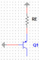
So, I've tried already using the ∏ hibrid model (with ro) and I obtained that the resistance seen from the collector is:
ro + (RE // [r∏/(hfe+1)])
Knowing that r∏ = hfe/gm and other expressions i tried to obtain the expression
ro*(1 + gm(RE//r∏))
but I didn't succeed.
-- // --
I will answear your question about how to determine the resistance seen from a viewpoint with a practical example of a CB amplifier.
Let's determine the resistance seen from the emitter terminal of the BJT (input resistance of the amplifier):
Rin = [r∏/(hfe+1)] // [ro + RC//RB1].
Let's determine the resistance seen from the output of the amplifier (output resistance of the amplifier):
Rout = [ (r∏/(hfe+1))//[RE1//RE2 + RE3] + ro ] // RB1 // RC.
The point here is just to emphasize that the transistor's output resistance sets the floor of the circuit's output resistance. For R_E significantly smaller than r_pi and for ß>>1, this simplifies to
Now, seeing this is a bit troubling, because I would not expect R_e to improve things so much.
But I can't help wondering how realistic this circuit is, it is shows no external collector resistance. For small R_E, the collector resistance, R_C, is basically in parallel with r_o. But for large R_E, that is not the case and so I have a feeling it would kill some of that factor.

 Facebook
 Google
 GitHub
 Linkedin