request - solution/schematic/hex

Thread Starter

arassel

Joined Nov 1, 2019
15
Hello,

If this is posted in the wrong section please correct me.

Would like a solution to a little project i'm working on :

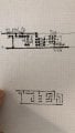
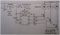
I need a circuit ( using a 12F629 ) that will get powered with 12v (from a car battery) and will light up 3 led strips consecutively with a delay of 0.3-0.4 seconds (and stay powered as long as the circuit has power).

Any feedback would be appreciated ..
 

ericgibbs

Joined Jan 29, 2010
18,766
hi arassel,
We would need details of the LED strips. current rating, operating voltage etc...
Have you programmed the PIC, if so which programming language.?

Need more info.
E
 

BobTPH

Joined Jun 5, 2013
8,807
He said he wanted Hex, so no, he wants us to do everything including the programming.

In other words he is asking us to thousands of dollars worth of consulting work for free.

Bob
 

Thread Starter

arassel

Joined Nov 1, 2019
15
Thanks for the reply, first i'd like to make you aware i know little to nothing about what i'm asking for, my electronic knowledge is scarce .. i'm some kind of scared about talking about it, not knowing exactly what i'm talking about :D .

please take into consideration i barely know what i'm doing ..

- ok so the 3 led strips are smd leds strips in series of 3 with a resistor , do i have to count them and get the current rating ?
- operating voltage is 12-14v, i'm trying to switch my taillights from bulb to led with a personal design. (also for changing from bulb to led what do i have to take into consideration?)

I've been looking alot for a solution to my idea as simple as possible .. i've attached pictures with what i've found and tried to build so far. any other simpler solution would be apreciated !

so far i've done this:

- i have the pic and the programmer, i used the hex i found and the programmer didnt give me any errors
- made the assembly as good as i could (please correct me if not)
- its not working
 

Attachments

Thread Starter

arassel

Joined Nov 1, 2019
15
In other words he is asking us to thousands of dollars worth of consulting work for free.

Bob
My apologies, not my intent, i've seen so many other shared projects completely detailed with hex and schematics far more complicated than my 3 led strips yocto-project, figured i wasnt asking for much, yet alone for thousands of dollars of consulting.
 

BobTPH

Joined Jun 5, 2013
8,807
I never would have guessed from your post that you already had the schematic and the hex code, since that was what you wete asking for.

You say it is not working. So what does it do?

Bob
 

Thread Starter

arassel

Joined Nov 1, 2019
15
You say it is not working. So what does it do?

Bob
when powering the circuit, nothing lights up, i will get a measuring tool today to see weather i'm not using the correct mosfets ... my thought is that the hex is not good .. but considering the most complex assembly i've ever done so was was a bike led blinker 15 years ago, i very much doubt my efforts in pulling this off.

first of all i dont know if the schematic for the soldering i did (last attachment) matches the schematic i found on the web (first attach) .. i dont even have refference to where i got the schematic and hex from, lost that trying to learn ho to program the pic :D.
 
Last edited:

BobTPH

Joined Jun 5, 2013
8,807
Make a copy of the schematic. Check each connection in the circuit you built and cross it off when it is verified. Make sure each set of connections (node) does not have any extra connections. Pay close attention to pinouts.


Unfortunately, you do not know if the hex is correct, no easy way to help you with that.

Verify that the strips work by using a wire to short across the source anddrain — that should light the up. Verify that the MOSFETs are working by putting 5V on the gate, that should also light the strips.

Bob
 

jpanhalt

Joined Jan 18, 2008
11,087
It's been awhile since I worked with the 12F629. Here's a (edit: raw ) disassembled version of that hex file:
Code:
    processor 12F629
    #include <P12F629.INC>
    __config 0x3194
;   _CPD_OFF & _CP_OFF & _BODEN_OFF & _MCLRE_OFF & _PWRTE_OFF & _WDT_OFF
;   & _INTRC_OSC_NOCLKOUT

; RAM-Variable
LRAM_0x5B equ 0x5B
LRAM_0x5C equ 0x5C
LRAM_0x5D equ 0x5D

; Program

    Org 0x0000

;   Reset-Vector
    GOTO LADR_0x000F

    Org 0x0003

LADR_0x0003
    MOVLW 0x80           ;   b'10000000'  d'128'
;   Interrupt-Vector
    BSF STATUS,RP0       ; !!Bank Register-Bank(0/1)-Select
    MOVWF TMR0           ; !!Bank!! TMR0 - OPTION_REG
    CLRF INTCON
    MOVLW 0x07           ;   b'00000111'  d'007'
    BCF STATUS,RP0       ; !!Bank Register-Bank(0/1)-Select
    MOVWF CMCON          ; !!Bank!! CMCON - VRCON
    CLRF GPIO            ; !!Bank!! GPIO - TRISIO
    MOVLW 0x38           ;   b'00111000'  d'056'  "8"
    BSF STATUS,RP0       ; !!Bank Register-Bank(0/1)-Select
    MOVWF GPIO           ; !!Bank!! GPIO - TRISIO
    RETURN
LADR_0x000F
    CALL LADR_0x0003
    BCF STATUS,RP0       ; !!Bank Register-Bank(0/1)-Select
    BSF GPIO,0           ; !!Bank!! GPIO - TRISIO
    MOVLW 0x06           ;   b'00000110'  d'006'
    MOVWF LRAM_0x5B
    MOVLW 0x13           ;   b'00010011'  d'019'
    MOVWF LRAM_0x5C
    MOVLW 0xAD           ;   b'10101101'  d'173'
    MOVWF LRAM_0x5D
LADR_0x0018
    DECFSZ LRAM_0x5D,F
    GOTO LADR_0x0018
    DECFSZ LRAM_0x5C,F
    GOTO LADR_0x0018
    DECFSZ LRAM_0x5B,F
    GOTO LADR_0x0018
    NOP
    NOP
    BSF GPIO,1           ; !!Bank!! GPIO - TRISIO
    MOVLW 0x06           ;   b'00000110'  d'006'
    MOVWF LRAM_0x5B
    MOVLW 0x13           ;   b'00010011'  d'019'
    MOVWF LRAM_0x5C
    MOVLW 0xAD           ;   b'10101101'  d'173'
    MOVWF LRAM_0x5D
LADR_0x0027
    DECFSZ LRAM_0x5D,F
    GOTO LADR_0x0027
    DECFSZ LRAM_0x5C,F
    GOTO LADR_0x0027
    DECFSZ LRAM_0x5B,F
    GOTO LADR_0x0027
    NOP
    NOP
    BSF GPIO,2           ; !!Bank!! GPIO - TRISIO
LADR_0x0030
    GOTO LADR_0x0030

    End
I am taking a look at the code, but it will take awhile.
 
Last edited by a moderator:

hexreader

Joined Apr 16, 2011
581
Hex file works OK on my home-made test board, except that 3 test LEDs light up at approximately 1 second intervals, not 0.3 to 0.4 seconds. .... but that is a good thing for testing - easier to work with....

PIC12F629 has a calibration word as the last instruction in memory. If that is missing, it can prevent the PIC from running.

I like BobTPH's idea of testing LED driver with no PIC fitted - proves the LED hardware.

Additionally you might wait 5 seconds after PIC power-up and check with multi-meter or oscilloscope that all three output pins are sitting at +5V (or probably a little less).
 

Thread Starter

arassel

Joined Nov 1, 2019
15
Thank you all for your reply's ... Had a revelation trying to explain myself the schematic i done .. i totally messed up the mosfets drain-gate-source on my schematic .. no way it could work .. redoing it all and come back with feedback.
 

jpanhalt

Joined Jan 18, 2008
11,087
Here's slightly "corrected" code FWIW. Note, when in Bank1, a write to TMR0 actually writes to OPTION_REG, and similarly, a write to GPIO writes to TRISIO. I madethose changes and added asterisks to the code that was commented out.

Code:
    processor 12F629
    #include <P12F629.INC>
    __config 0x3194
;   _CPD_OFF & _CP_OFF & _BODEN_OFF & _MCLRE_OFF & _PWRTE_OFF & _WDT_OFF
;   & _INTRC_OSC_NOCLKOUT

; RAM-Variable
LRAM_0x5B equ 0x5B
LRAM_0x5C equ 0x5C
LRAM_0x5D equ 0x5D

; Program

    Org 0x0000

;   Reset-Vector
    GOTO LADR_0x000F

    Org 0x0003

LADR_0x0003
    MOVLW 0x80           ;
;   Interrupt-Vector
    BSF STATUS,RP0       ;|B1
;   MOVWF TMR0*
    MOVWF OPTION_REG     ;TMR0 = OPTION_REG when in |B1
    CLRF INTCON          ;
    MOVLW 0x07           ;
    BCF STATUS,RP0       ;|B0
    MOVWF CMCON          ;turn off comparators
    CLRF GPIO            ;
    MOVLW 0x38           ; b'00111000'
    BSF STATUS,RP0       ;|B1
;   MOVWF GPI0*
    MOVWF TRISIO         ;GPIO = TRISIO when in |B1, sets GPIO 0,1,2 to output
    RETURN
LADR_0x000F
    CALL LADR_0x0003
    BCF STATUS,RP0       ;|B0
    BSF GPIO,0           ;
    MOVLW 0x06           ;b'00000110'
    MOVWF LRAM_0x5B
    MOVLW 0x13           ;b'00010011' 
    MOVWF LRAM_0x5C
    MOVLW 0xAD           ;b'10101101' 
    MOVWF LRAM_0x5D
LADR_0x0018
    DECFSZ LRAM_0x5D,F
    GOTO LADR_0x0018
    DECFSZ LRAM_0x5C,F
    GOTO LADR_0x0018
    DECFSZ LRAM_0x5B,F
    GOTO LADR_0x0018
    NOP
    NOP
    BSF GPIO,1           ;
    MOVLW 0x06           ;b'00000110' 
    MOVWF LRAM_0x5B
    MOVLW 0x13           ;b'00010011' 
    MOVWF LRAM_0x5C
    MOVLW 0xAD           ;b'10101101' 
    MOVWF LRAM_0x5D
LADR_0x0027
    DECFSZ LRAM_0x5D,F
    GOTO LADR_0x0027
    DECFSZ LRAM_0x5C,F
    GOTO LADR_0x0027
    DECFSZ LRAM_0x5B,F
    GOTO LADR_0x0027
    NOP
    NOP
    BSF GPIO,2           ;
LADR_0x0030
    GOTO LADR_0x0030

    End
The code should work and compiles fine, except the delays have not been checked.
 

jpanhalt

Joined Jan 18, 2008
11,087
I just simulated the above program at 4 MHz using MPLAB SIM. First, the led attached to GPIO,0 turns on. After a delay of 1 second (1.00000x seconds), the led attached to GPIO,1 turns on, then after another delay of 1 second, the led attached to GPIO,2 turns on. It then idles in that state.

Those are in accord with @hexreader 's observations and suggest that the TS's expectations for delay are wrong. If he wants shorter intervals, that is easily fixed.
 

Thread Starter

arassel

Joined Nov 1, 2019
15
Thanks alot for the help guys, i'm grateful for the effort in your reply's .. will try to redo the assembly after work ..


I just simulated the above program at 4 MHz using MPLAB SIM. First, the led attached to GPIO,0 turns on. After a delay of 1 second (1.00000x seconds), the led attached to GPIO,1 turns on, then after another delay of 1 second, the led attached to GPIO,2 turns on. It then idles in that state.

Those are in accord with @hexreader 's observations and suggest that the TS's expectations for delay are wrong. If he wants shorter intervals, that is easily fixed.
.. meanwhile

- the led strips i want to use have 21 smd leds eatch .. can the pic handle the amps ?

- what do i need to use to compile the code ? that gives me the hex file i need to program in the pic right ? (again, never done this before please dont stone me ) what do i need to change to make the delay at 300 or 400 ms instead of 1 second ? what i want is when circuit is powered 1st strip to light up, 0.3 seconds later 2nd strip lights up, 0.3 seconds after 3rd strip lights up and all stay on from the moment they are turned on by the pic.

- is there any delay from the moment of the circuit getting power to do the light up ?
 

jpanhalt

Joined Jan 18, 2008
11,087
.. meanwhile
- the led strips i want to use have 21 smd leds eatch .. can the pic handle the amps ?
The PIC cannot run that many LED's DIRECTLY, but that is the purpose of the mosfets. Be sure you have logic level mosfets, and there is no reasonable limit to what you can run.

- what do i need to use to compile the code ? that gives me the hex file i need to program in the pic right ? (again, never done this before please dont stone me ) what do i need to change to make the delay at 300 or 400 ms instead of 1 second ?
You do not need to compile the code. What you have works. The code I posted simply converted that hex file to Assembly language. There are a few "quirks" in the way such disassembly works. I changed them to make it more readable. They were not errors. If you want to compile it, you will need to download a compiler from Microchip. They are generally free for compiling Assembly. I use MPLAB 8.92, which includs the compiler. If you really want the delay to be different, I or many others here can do that for you and post the code. It is really no big deal. However, the original author of that code carefully planned it to be 1 second. Anyone who does that can easily post the new hex code.

what i want is when circuit is powered 1st strip to light up, 0.3 seconds later 2nd strip lights up, 0.3 seconds after 3rd strip lights up and all stay on from the moment they are turned on by the pic.
That is what the current code does, except instead of 0.3 seconds, it is 1 second. 0.3 seconds is really quite brief, but if that is what you need, just say so.

- is there any delay from the moment of the circuit getting power to do the light up ?
As I recall, there is a short delay of about 18 microseconds, which is not perceptible by humans. Your switch may bounce that long. It can be shortened a little but not made "zero."
 

Thread Starter

arassel

Joined Nov 1, 2019
15
@ jpanhalt thanks again, really appreciate you taking the time for me ... i may have to ask if you can change the code, make 2 different hex files ?

these are the mosfets .. i bent the legs to get less routing on the circuit board i drawn after the schematic, tried different routes, but i dont have much space so i went for the leg bending one :D.
 

Attachments

jpanhalt

Joined Jan 18, 2008
11,087
I cannot make out clearly the whole ID on the mosfets. Please tell . Generally, the pins are GDS in that order, and the metal tab is electrically connected to the middle pin.

I'll work on shortening the delays.

John
 

bertus

Joined Apr 5, 2008
22,270
Hello,

How are you driving the mosfet?
A full schematic would give us the information needed.
If the gate voltage is to low, the drain current will be to low.

T2916_drain current versus gate voltage.png

Bertus
 

Attachments

Thread Starter

arassel

Joined Nov 1, 2019
15
I cannot make out clearly the whole ID on the mosfets. Please tell . Generally, the pins are GDS in that order, and the metal tab is electrically connected to the middle pin.
this is the data sheet of the mosfet.


I'll work on shortening the delays.

John
is it possible to make another hex file from the one i got but modify it to be with 0.5 s delay but to keep the strips light up only for just 0.3 seconds ? so the operation order would be :

power to circuit - 1 led lights up only for 0.3s - 2nd led strip lights up 0.2s after the 1st strip for another 0.3s - 3rd led strip lights up with 0.2s from the 2nd for 0.3s.

hope i made myself clear on that

o_O
 

Thread Starter

arassel

Joined Nov 1, 2019
15
Hello,

How are you driving the mosfet?
A full schematic would give us the information needed.
If the gate voltage is to low, the drain current will be to low.
the only schematic i have is the one i found on the internets here, posted it earlyer, attached it again now
 

Attachments

Top