I see the confusion.
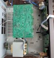
The actual board does not match what is shown in the Service Manual. I will try to find the correct documentation.
Is there a board revision number printed on the board?
Edit:
Sorry, I think we are looking at the board from the reverse side.
Give me some time to analyze this situation.
There are problems with both channels. We have to look at DC voltages before the power amp stage.
The LEFT channel schematic is shown. The RIGHT channel is a copy of the LEFT channel.
Locate TP401 (LEFT channel) and TP402 (RIGHT channel). Measure the voltage at pins 1, 2, and 3 on both TP401 and TP402. The expected voltages should be low, less than 1 V or close to 0 V.
TP401 and TP402 are shown. You will have to reverse the image.
Locate TP401 (LEFT channel) and TP402 (RIGHT channel). Measure the voltage at pins 1, 2, and 3 on both TP401 and TP402. The expected voltages should be low, less than 1 V or close to 0 V.
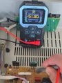
The voltage on TP401 and TP402 is approximately -15 V across all pins. After a few seconds, it increases to -57 V across all pins. The measurement was taken with one probe connected to ground and the other to the pins.
the measurement according to the instructions is below 1v
There should be a couple of voltage regulators somewhere on the board (7815 and 7915). Check for poor solder connections on these regulators. This is a common failure point.
@MrChips
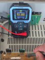
I'm afraid the measurements so far are incorrect. I connected one multimeter probe to the speaker's negative output, thinking it was grounded.
Connecting the probe directly to the amplifier chassis gives different results.
I apologize for misleading you.
All the points I measured earlier are now around 0V.
That's fine. We need to measure the supply voltages on IC501 and IC502.
Here are four points to measure:
#1 IC501 pin-8 at lower leg of R515 (it could be a jumper)
#2 IC501 pin-4 at C515 or Q503 emitter
#3 IC502 pin-8
#4 IC502 pin-4 at C516 or Q504 emitter
You could measure the voltages directly on the IC pins if you are careful not to create any shorts when probing around a live circuit.
Are you comfortable reading the circuit schematics and matching it with the PCB layout (reversed image)?
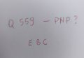
We need get the voltage readings of B, C, E of Q501, Q502, Q503, Q504.
If you cannot safely make contact to the transistor leads, look at the shematics and PCB layout. You will be able to find other components that share the same load.
Again, don't make things worse by causing any accidental shorts.
All voltage measurements are made with respect to GND unless specified differently.
If the transistors have been removed, measure at the pads with respect to GND.
If the transistors are installed, make the measurement any more convenient component connected at the same node.
LEFT and RIGHT channels are shown below for convenience.
 Facebook
 Google
 GitHub
 Linkedin


.png")
 I connected one multimeter probe to the speaker's negative output, thinking it was grounded.