Request for help in repairing Technics SU-V90D

MrChips

Joined Oct 2, 2009
34,887
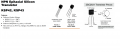
Z551 and Z552 are emitter bias resistors.
Their condition (good or bad) does not affect the assessment and evaluation of the circuit at this point in time.
It is possible that Z552 blew when Q558 and Q560 both shorted.

We are trying to establish correct supply voltages at IC501 and IC502.

We were measuring supply voltages and you encountered fluctuating readings. Has this been resolved?
Even if the voltages are now stable, we have not identified why you were getting unstable readings. It would be instructive to find out what was the cause of this.
What caused it?
What was done to resolve this?
 

Thread Starter

KaMel88

Joined May 11, 2026
34
We were measuring supply voltages and you encountered fluctuating readings. Has this been resolved?

check post no. 59
https://forum.allaboutcircuits.com/...epairing-technics-su-v90d.210443/post-2037415
Even if the voltages are now stable, we have not identified why you were getting unstable readings. It would be instructive to find out what was the cause of this.
What caused it?
What was done to resolve this?
I think we're at a standstill for now, apart from identifying a few damaged elements :(
 

MrChips

Joined Oct 2, 2009
34,887
I think we're at a standstill for now, apart from identifying a few damaged elements :(
I don't give up so easily.
The proper diagnostic approach is to test functionality, not to search for damaged elements.

I have steered you in the right direction. You need to stay on track and stay focused.

The first step is to verify supply voltages.

You should see the same stable V+ voltage at the collectors of Q501, Q502, Q553, Q557, Q554, Q559.
Similarly, you should see the same stable V- voltage at the collectors of Q503, Q504, Q555, Q556, Q560.

If that is not the case, then there is something wrong with your testing procedures.
 

Thread Starter

KaMel88

Joined May 11, 2026
34
If that is not the case, then there is something wrong with your testing procedures.
That's right, it turned out that the cause of the unstable voltages was the lack of a board with outputs :oops:

New measurements :

Q557 - B: -4.2v C: 52v E: 0v
Q559 - B: -5,4v C: -52v E: 0v
Q560 - B: 0v C: -52v E: 0v
Q558 - B: 0v C: 52v E: 0v

TP401, TP402 all pins 0v

IC501 - pin 8 : 7,7v
IC501 - pin 4 : -7,7v
IC502 - pin 8 : 0v
IC502 - pin 4 : 0v

Q504 - E: 0v C: -53v B: -8,4v
Q502 - E: 0v C: 52v B: 8,4v
Q503 - E: -7,7v C: -52v B: -8,3v
Q501 - E: 7,7v C: 52v B: 8,3V
 

Attachments

MrChips

Joined Oct 2, 2009
34,887
Thanks for these measurements. We are back on track.

We are going to focus on the LEFT channel.

Measure the voltages at Q551, B C E.
Note that it may be easier to measure these at R553 and R555.
 

MrChips

Joined Oct 2, 2009
34,887
In terms of creating a shopping list for possible replacements, here is what I would suggest, with minimum quantity in braces (QTY). You can buy more for spares.

(4) IC501, IC502 M5219P, try RC4558P
(2) Q502 2SC2631
(2) Q504 2SA1123
(2) Q551, Q552 2SC1815
(2) Q558 2SC3281
(2) Q560 2SA1302
(2) R560, R564 2.2Ω 2W
(2) R568 0.1Ω 0.25W
(2) Z552 0.22Ω 5W wire-wound
 

MrChips

Joined Oct 2, 2009
34,887
We don't yet know which components caused the catastrophic failure. Our focus is on getting the LEFT channel working so that we can get some real live voltages. I am contemplating replacing Q551 in the LEFT channel as a first stab at it.

Sooner or later you will need to buy components. Rather than placing multiple orders, it would be better to get them all at once in order to save time and shipping charges.

You will have a hard time replacing Z552. I am suggesting getting two 0.22Ω 5W resistors to replace the one dual resistor.
 
Top