 Facebook
 Google
 GitHub
 Linkedin
Hi all.
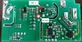
I am thinking about a way to replace a push button switch with a transistor or optocoupler (but not relay) within a circuit.
The push button is that in a sonoff basic wifi switch.
What I want is, when the mains 220V AC is connected to our designed circuit, after 5-10s it should makes a pulse triggering a transistor or optocoupler that is connected accross the push butttom.
And when the mains 220V Ac is disconnected, it should also make pulse triggering it again but it is not a must to wait 5-10s when electricity goes off.
So, when electricity goes ON, after few second the electronic circuit should trigger that switch electronically (not mechanically through push button). And the same thing should happen again when electricity goes OFF.
There will be another source of 220V AC available all the time. It looks like we will hack this sonoff basic switch.
I'm looking to make it as simple as possible and even try to place the circuit inside the sonoff basic switch encloser.
I was trying to make the circuit using only capacitors, resistors and transistors, without 555 timer and relays, and hope it could be done like that.
Best Regards,
Hazim
Attachments
-
 812.6 KB Views: 19
 -
 474 KB Views: 18


