Repair thermoelectric cooler PSU HYS80-12J2B/220V

Thread Starter

BigDave19070

Joined Sep 25, 2023
13
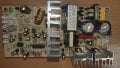
So I got a wine chiller that has got the 0757-83835908 PCB in it, looks similar to some of yours

It is dead no signs of life at all, I have replaced all the electrolytic caps, plus the 2 large transistors and the schottky diode.
(all parts with yellow dots are new parts)

But it is still dead, got voltages on the large transistors but nothing on the output side.

I hooked up a bench top supply to the DC power rail and it starts to work,

Everything in the AC side looks and measure ok, 4 diodes in bridge look ok, 2ohm resistors are ok, so are all the other resistors

Anybody got any ideas, switch mode supplies aint really my thing, I have ordered 2 x 2SC1815's just in case

Also meant to ask there is a PCB jumper inside one of the input output connectors on the left, CN7 marked K, any ideas why it is linked out?

20230928_153639.jpg
 

Dodgydave

Joined Jun 22, 2012
11,395
These switch-mode PSUs are not the best to fix, this model uses a TL494 chip (16 pins) to pulse the mains and converts it to low voltage DC.
It works by using the two transistors on the heatsinks to pulse the large transformer across the mains rectified DC , at high frequencies and is rectified by the twin diode on the other heatsink , the output voltage is controlled by the chip, set by resistors.

First check the DC supply on the large capacitors should be around 200V, one transistor will be connected to the positive side and the other one on the negative side, these are fired alternately by the chip.

Here's the correct diagram.

1612325334869.png1696260541475.png
 
Last edited:

Thread Starter

BigDave19070

Joined Sep 25, 2023
13
can anyone suggest a replacement pcb for the one shown in post one, I have changed all electro caps, various transistors & schottky & IC, its still dead on DC side, I have 300V across the large caps, but nothing past the transformers, I give up, switch modes are not my friends lol
 

Attachments

Thread Starter

BigDave19070

Joined Sep 25, 2023
13
Updated the correct diagram above, If it's any good.
Cheers mate, Still not sure if it is 100% the right diagram, but its close enough (C12 and C15 are 220uF caps 250v, this diagram uses different numbers), but as I say close enough i guess

I connected a benchtop supply to the output of the Schottky device, (i had to remove the cooling device due to the current it draws) and the machine fires up fine (no cooling obviously), so deffo a primary switch mode issue,

Not sure where to start looking, 165V DC on the two large transistors, but not seeing much else where

Cheers anywhere
 

Thread Starter

BigDave19070

Joined Sep 25, 2023
13
All I can say is check the transistors, any diodes, and low value resistors, change the two small caps .
Cheers Dave, I will take another look, which 2 small caps do you talk about? my original C17 looked like it had got quite warm

Question, you seem very knowledgeable on these PCBs and units, so my initial thought was hook up another external supply to the output of the schottky (basically doing away with mains AC side of the board), and feed it with say 12.5V DC, but looking at the diagram this will pump 12.5V into the the 2 fans and the peltier, so running them all the time,

Question is does the output voltage change from the schottky depending on sensor inputs and user requirements from front panel. As doing it my way it look like it will run and run at full power?

Do you have any test voltages on any part of the diagram, I am a electronic tech but switch modes do my head in

Cheers again Dave

12.5v.png
 

Dodgydave

Joined Jun 22, 2012
11,395
The Idea is when the temperature is goes lower than the set temperature, the LM358 chip puts an high output to pin 1 of the TL494 to alter the pwm signal, which lowers the output voltage, so the peltier will be slowed down or stop, .

So if you want to use a separate 12V supply then you need to modify the temperature controller with a relay or otherwise swap the whole pcb.

IMG_20231012_091834.png
 

Thread Starter

BigDave19070

Joined Sep 25, 2023
13
Nice one mate, thanks for that, I knew it wasnt gonna be as easy as stuffing a power brick in there lol

Makes total sense wot u said, u also mentioned two small caps in an earlier message, have you got any idea of circuit board reference numbers for them.

Cheers again
 

Dodgydave

Joined Jun 22, 2012
11,395
Yes on the circuit diagram of the primary side, C14 and C15, on your pcb I think it's C13 and i can't see the other one it's behind the transformer, you've put a yellow spot on it.
These are a pain in the A** to fix , it's easier to get it replaced with a new pcb, .
 

Thread Starter

BigDave19070

Joined Sep 25, 2023
13
Yes on the circuit diagram of the primary side, C14 and C15, on your pcb I think it's C13 and i can't see the other one it's behind the transformer, you've put a yellow spot on it.
These are a pain in the A** to fix , it's easier to get it replaced with a new pcb, .

Dave your right Pain in the friggin A*** indeed

Gonna look to replace it, struggling to find an exact replacement
But I see lots of people selling what looks close to it, FX102 or FX101
Looking at the 220VAC 12.5DC 70W boards

https://www.aliexpress.com/item/100...189ebad46b1a56a0a1a3f46564e&afSmartRedirect=y


I dont suppose you know if these are good, or do you have any other suggestions,

Again thanks for your help dude, from one red to another


Dave
 

Dodgydave

Joined Jun 22, 2012
11,395
Dave your right Pain in the friggin A*** indeed

Gonna look to replace it, struggling to find an exact replacement
But I see lots of people selling what looks close to it, FX102 or FX101
Looking at the 220VAC 12.5DC 70W boards

https://www.aliexpress.com/item/100...189ebad46b1a56a0a1a3f46564e&afSmartRedirect=y


I dont suppose you know if these are good, or do you have any other suggestions,

Again thanks for your help dude, from one red to another


Dave
I can't recommend any of these, but as long as it has the relevant connections for the peltier and fan, thermistors etc, it should work, higher wattage is best.
Good luck,
 

Thread Starter

BigDave19070

Joined Sep 25, 2023
13
Just thought I would share my story so far, couldn't find an exact PCB replacement so I went and bought a FX102 PCB, it was cheap enough and thought I would give it a go

So to start with there were a few sockets that needed taking off and rotating as the polarity was different to my plugs on my chiller.
fx102.jpg

(1) Blue circle socket rotated 180 degree so '+' & '-' was correct for the power to the display panel

(2) Yellow circles are fans sockets, again ground and positive were reversed so took them off rotated 180 degrees re soldered and sorted, still not sure which fan plug goes in which socket as on previous board they shared the same +'ve power rail, on this board the live is not common to both sockets??

(3) Got a red and green LED on this board, any ideas what these are indicating?? Red I have on all the time, don't see much of green, I get a flash on green LED on power up??

(4) After doing all the above initially it wouldn't turn the peltier on? But I worked it out that the reference voltage on the pin 2 of the LM358 was set too high, so I changed RA2 (red circle) to a lower value resistor, ( I will have to get the value again for anyone else) this reduced the reference voltage on PIN2, now turning the temperature up and down adjusts the voltage on PIN3 to above and below the reference voltage on PIN2 of LM358 which in turns PIN1 on LM358 positive when it requires to be chilled.

(5) Other things I have noticed the voltage on the peltier drops to like +2 volts on the spade connectors when I require chill, (I will have to de-solder and see what it reads with it disconnected. Is it normal to drive it down so low??


Any help to points (2), (3) and (5) would be good to hear

Cheers guys and happy to share my findings with you, lets get these damn chillers working again lol


Dave
Cardiff
 

wayneh

Joined Sep 9, 2010
18,087
(5) Other things I have noticed the voltage on the peltier drops to like +2 volts on the spade connectors when I require chill, (I will have to de-solder and see what it reads with it disconnected. Is it normal to drive it down so low??
No, I don't think the voltage should collapse like that. Two volts will drive only about two amps through the chip and that's far below its rating. It may be more efficient that way but will likely not achieve the ∆T or heat removal that you want. I do not think these PS boards are smart enough to provide a PWM (proportional) signal to the chip, they're either full on or off like a typical thermostat.
 

Thread Starter

BigDave19070

Joined Sep 25, 2023
13
Your right, its either on or off, (it was my fault see the bit below on the OP amp issue I had)

So good news I got the FX102 to work on my fridge (HUSKY HN6) as the original PCB was no longer being sold.

It needed a little tinkering but got there in the end.

Things I had to do:

3 of the headers were the wrong way around for my chiller, so de-soldered them, rotated them by 180degress and re-soldered them, that was both fan headers, and the temperature feedback sensor NTC header. I needed to use the top two pins of the 3 way socket for my + - connection for the front panel power.

Mains header socket was slightly different as my mains header wouldn't fit, so swapped it with the socket from original PCB

The other strange bit was a had to disconnect / cut Pins 5 6 and 7 from the OP amp, (the LM358), I guess these pins are for dual temperature zoned chillers, with 5 6 and 7 connected it wouldn't call for chill, once disconnected it worked first time.

FX102.jpg

So good news all working again, just one little question left.

On my original PCB both fans had there own sockets but looking at the PCB they shared the same track work, so both fans were either on or off (or maybe running at slower speed)

Now the FX102 has a slightly different setup, it has one black socket and one white socket, there tracks are not common to each other.

When chilling both fans run at full speed, that I understand, but on standby, i.e. waiting to get the next signal to chill, one fan runs slowly and the other is off.

Question which fan should be running in standby mode, the one that does inside the cabinet or the one below the PCB sat on the big heat sink

Any ideas

Cheers again for all your help guys

Dave
 

wayneh

Joined Sep 9, 2010
18,087
Question which fan should be running in standby mode, the one that does inside the cabinet or the one below the PCB sat on the big heat sink
Tough call, and I don't know. The biggest issue with any Peltier device is shedding heat, so it makes some sense to me that the exterior fan would have extra run time. But on the other hand, keeping the chamber air moving would help chill the contents faster and keep the temperature more consistent throughout the chamber.

Great job getting it going again!
 

nyx1024

Joined Dec 28, 2023
5
Thank you BigDave for all the information, i had the same issue and I followed what you did it worked perfectly for me. Trying to figure out the issue addressed with the Peltier when it drops to +2, do you have any insight into that? and the resistor that you changed, what was the value of the resistor? is it (brown yellow black red) now?
 

Thread Starter

BigDave19070

Joined Sep 25, 2023
13
Hey Nyx1024

So on my earlier post - post #14, Forget the lines (4) and (5), for me it was all to do with the secondary input on the 8 pin IC, it was causing all sorts of issues,

So if your chiller doesn't have a secondary NTC sensor I would suggest cutting pins 5 6 and 7 (for me I de-soldered the chip, removed it and bent pins 5 6 and 7 90degrees so they didn't go through the board holes and re-soldered the other 5 pins as normal). So after removing the pins I also went with the stock resistor in position RA2 and it worked fine

Also it is important the Peltier is connected when taking voltage readings, this again was a school boy error I made, when it is connected it makes a massive difference to voltages across the board.

This got my Husky working again, it may be different for other makes and models

Let me know how you get on


Dave
 
Top