Remote control of rheostat (or motor)

Thread Starter

almiller

Joined May 20, 2022
18
Yeah for this project I definitely want the cart to stay in front of me. As I play/walk the course my focus is always what's in front of me (where's my ball and how far is it to the green).

The cart already propels by itself with a potentiometer knob on the handle and my original problem was simply that I have to
keep my hand on the handle at all times because I'm constantly adjusting the speed up/down. If it followed my and I had to look back every 5 seconds to check on it that would be just as distracting.

I'd also note that having a small IR remote that allows me to "disable" the automatic speed if very important.
While playing there are many instances where I would not want the cart to automatically start rolling.
How else would the cart know to stop when I walk up to a sand bunker or the putting green or the lake where my ball usually ends up.

While I was trying to get everything mounted into a small box to mount onto the cart frame I broke my LiDAR sensor.
I also had issues getting the servo motor that turns the shaft of the potentiometer to be at the correct angle. I can turn the servo 0 - 270 degrees which was very close to the range that the potentiometer turns but the motor has to be mounted at an exact angle for that to work.

So I decided to try this instead:

  1. 1. Raspberry Pi Zero W or my Arduino UNO (both are smaller than the older Pi 3B+)
    I would still need code/logic that decides how to adjust the potentiometer,
    I'd also need code/logic that reads the IR codes from my remote so I can override the "automatic" speeds
  2. 2. Adafruit VL53L1X TOF Distance Sensor
  3. 3. Adafruit DS3502 I2C Digital 10K Potentiometer
    With this I'd be able to digitally control the existing potentiometer without having the servo turn the knob, correct?
    Then I don't need a servo or a PWM driver board

For #1 I don't know what's easier/better Arduino or RPI. I'm just more familiar with the Pi.
 
Last edited:

MisterBill2

Joined Jan 23, 2018
28,068
The concept that I proposed was a system with the cart staying ahead a few feet while still being manually aimed by the user as the direction of travel needed to change. So the distance sensing beam window would be fairly narrow.
Whenever there was a loss of the return beam the drive would stop. this puts the user in rather good control, and should be fairly fail safe. The sensor would work to hold a distance, not a speed, and so precise control of speed is not a requirement. And it really does not need much active control from the user, so it could be using just a reflected beam, not an IR command signal. It would be a lot simpler than some want to make it.
 

strantor

Joined Oct 3, 2010
6,875
For #1 I don't know what's easier/better Arduino or RPI. I'm just more familiar with the Pi.
Considering the progress you've already made on the other Pi i would lean toward the Pi. What happened to the camera and OpenCV? Is that still part of the plan? That was one the cooler parts of the project IMO. If that's still part of the plan then definitely I vote Pi.
  1. 3. Adafruit DS3502 I2C Digital 10K Potentiometer
    With this I'd be able to digitally control the existing potentiometer without having the servo turn the knob, correct?
    Then I don't need a servo or a PWM driver board
Correct. I would use a toggle switch to change between the existing handle grip and the digipot. That way you can still have a "manual mode" if things act up.
 

Thread Starter

almiller

Joined May 20, 2022
18
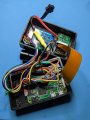
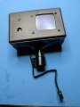
Thanks, I'm continuing with the RPi Zero and made some progress. Got all my components mounted into a small box.


  • PXL_20220722_211731403.jpgPXL_20220722_212555355.jpg

Unfortunately I fried GPIO pin 2 (I2C SDA) so I'm trying to setup another (sw-controlled) i2c bus on a different gpio-pair.

Correct. I would use a toggle switch to change between the existing handle grip and the digipot. That way you can still have a "manual mode" if things act up.
So there are 4 resistor pins on the "digipot" (per https://learn.adafruit.com/ds3502-i2c-potentiometer/pinouts)
RL, RW, RH, and V+

I'm not sure where these resistor pins need to go to on the board where the existing "manual pot" is?
There are only 3 wires coming from the manual pot; with markings that look like L, X, and "long dash"?

Also not sure how I'd insert a toggle switch between the digi and manual pots?

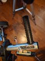
Here's a photo of the manual pot with the 3 wires to the lcd-panel.

PXL_20220722_221324034.jpg
 

Thread Starter

almiller

Joined May 20, 2022
18
Is it te manual pot that seems to have only four speeds??
Yes, if I measure the voltage going into the motor while I slowly turn the manual pot from 0 to max,
the motor increases its speed at "roughly" these steps: 4.1, 5.3, 6.6, 8.9, and 11.3 volts.
The gaps don't seem consistent (should they be), also don't know any specs of the pot or the motor.
 

Thread Starter

almiller

Joined May 20, 2022
18
Yes, if I measure the voltage going into the motor while I slowly turn the manual pot from 0 to max,
the motor increases its speed at "roughly" these steps: 4.1, 5.3, 6.6, 8.9, and 11.3 volts.
The gaps don't seem consistent (should they be), also don't know any specs of the pot or the motor.
I meant the gaps in the voltages don't seem consistent. Normally I'm toggling the speed between the middle 2.
Ideally I'd like more speeds in between but that probably requires a new motor (project for another day).
FromToincrease of
4.1v5.3v (almost too slow to walk)1.2v
5.3v6.6v1.3v
6.6v8.9v2.3v
8.9v11.3v (have to jog to keep up)2.4v

I was able to get my I2C devices working again by using a different gpio pair. Added this to /boot/config.txt
and I can access my Digital Potentiometer (DS3502) and Distance Sensor (VL53L1X) again. I also had to add
1K resistors to the lines on pins 5 & 6.

# fried gpio2 (sda) so using software i2c bus 3 on pins 29,31
dtoverlay=i2c-gpio,bus=3,i2c_gpio_sda=5,i2c_gpio_scl=6


Everything is neatly back in the box for now (I'll have to figure out a better permanent solution later)
and I'm able to measure distance and write to the OLED from C (Python is way too slow on the Zero).
 

ebeowulf17

Joined Aug 12, 2014
3,307
Yes, if I measure the voltage going into the motor while I slowly turn the manual pot from 0 to max,
the motor increases its speed at "roughly" these steps: 4.1, 5.3, 6.6, 8.9, and 11.3 volts.
The gaps don't seem consistent (should they be), also don't know any specs of the pot or the motor.
Before you get any farther into trying to wire digipots or anything else, I'd strongly recommend you make sure you know where the problem is at.

What you've done so far is measure voltage at the *motor* while sweeping the manual pot, and you've come to the conclusion that the manual pot only moves in a few (5, or maybe 6 if you include "off") discrete increments. That is highly unlikely. What is much more likely is that you've got a normal manual potentiometer, which sweeps pretty smoothly, in analog fashion, through all voltages, and that the control circuitry interprets that and chops it up into a few discrete zones. The control circuitry then controls the motor with PWM control (as others have already mentioned) with a few discrete speeds to choose from. If this is the case, adding a digipot to replace the manual pot would give you remote control via RPi, but it would not give you any more speed choices.

Are you ok with still being limited to the existing stepped speed choices? Your RPi logic could toggle between the two best speeds and always keep the cart close to you, so maybe it wouldn't matter if you had smoother speed control or not, as long as the computer is doing the incessant toggling back and forth between the two speeds closest to what you actually need in any given moment.

Anyway, if discrete speeds vs. smooth speed control doesn't matter to you, then feel free to ignore this post. But, if part of your goal is to achieve smoother speed control, then you should isolate the problem first. The way to do that would be to measure the voltages at the existing potentiometer, not at the motor, while sweeping the pot. If you find discrete steps there too, I'd be pretty surprised, but that would imply that it was moving in those discrete steps, and that there's a chance that replacing it with a higher-resolution digipot *might* improve the resolution of your speed control. On the other hand, if you find that the actual potentiometer moves in smooth, analog fashion, then that would mean that you can't achieve smoother, tighter speed control without replacing some or all of the control circuitry.
 

ebeowulf17

Joined Aug 12, 2014
3,307
P.S. regardless of whether you care about smooth vs. stepped speed control, you should still measure voltages at the pot while sweeping it and tag each of the three wires. You should find that there are two wires that have a constant voltage between them, regardless of pot position. Mark the higher voltage one H and the lower one L. The remaining wire will be the one whose voltage (as measured relative to L or H) changes when you turn the pot. Mark this one W.

Now you've got High, Low, and Wiper wires identified and marked as a first step towards wiring in the digipot. Once these wires are identified, adding the digipot and toggle selector switch is pretty easy. You'll directly connect H and L wires to corresponding pins on digipot (while also leaving them connected to manual pot.) Then, for the W wires, you'll connect the common pin on an SPDT toggle switch to the W wire on the circuit board. Next connect the W wire from the pot to one switched pin on the switch, and the W pin from the digipot to the other pin on the switch.

Hopefully that all makes sense. If not, I can whip up a little drawing to help clarify... but I'm a little busy today, so I'm not sure how soon I could get it done.
 

Thread Starter

almiller

Joined May 20, 2022
18
P.S. regardless of whether you care about smooth vs. stepped speed control, you should still measure voltages at the pot while sweeping it and tag each of the three wires.
Yes, that makes sense. By measuring at the motor I was ignoring whatever the existing control unit is doing.
I wasn't looking for finer grained speed control but while I'm at it might as well do that if possible.
And I'd like understand how the pot works.

You should find that there are two wires that have a constant voltage between them, regardless of pot position. Mark the higher voltage one H and the lower one L. The remaining wire will be the one whose voltage (as measured relative to L or H) changes when you turn the pot. Mark this one W.
I didn't see that behavior. When I measured the pot outputs for the 3 wire-combinations A-B, A-C, & B-C and see this:
Wire CombinationWhen turning pot from 0 to max
Wire-A (green) & Wire-B (blue)Voltage increases from 0.000 to 4.057
Wire-A (green) & Wire-C (purple)Voltage decreases from 4.433 to 4.059
Wire-B (blue) & Wire-C (purple)Voltage decreases from 4.433 to 0.001

Here's a video of how I got those values https://photos.app.goo.gl/SMtoi2TUCMQjGskN9
 

ebeowulf17

Joined Aug 12, 2014
3,307
I didn't see that behavior. When I measured the pot outputs for the 3 wire-combinations A-B, A-C, & B-C and see this:
It looks to me like A (green) and C (purple) are your low and high, making B (blue) the wiper.

The difference between 4.433 and 4.059V on your A to C measurements probably represents voltage sag as the motor starts drawing more and more power and the battery voltage supplied to the rest of the system sags a little. If you wanted to test my theory, you could poke around and figure out where some wires with the raw battery voltage are, and monitor that voltage from min to max pot positions. I bet you'll see about 8-9% of sag there, just like on the supply voltage to the pot.

I think C is high and A is low, but you should double-check my logic on that.
 

Gofball

Joined Feb 10, 2024
1
Every once in a while someone comes along who sounds savvy enough that they get talked to like they have a basic understanding when they don't. I think you might be one of them. So let me break this down.

PWM = pluse width modulation. Let's say your battery voltage is 24V and when you apply 24V to the motor your cart cruises at sprinting speed. You want it to go about 25% of max, so you want to give the motor 6V instead of 24V. But your battery is 24V, not 6V. What you can do is turn the motor off and on really fast (a few thousand times per second, AKA a few kHz). You turn it on (apply the full 24V) for 0.0001 seconds and then you turn it off for 0.0003 seconds and then on for another 0.0001 seconds and on and on repeatedly. What you're doing is PWM. You're pulsing the motor with a PWM voltage. Your PWM duty cycle (the ratio of on : off time) is 25%
0.0001s ÷ (0.0001s + 0.0003s) = 0.25
This is in effect the same thing as applying 6V to it.
This is a very efficient way to control a motor and most likely the way your existing controller board already works.

The other suggestion to use a high power/low-resistance rheostat in series with the motor is wasteful. It is a viable solution and was employed for years in the ride-on golf carts but has been entirely abandoned as far as I know.

If you want the water analogy here it goes... say you want to fill a bucket at 10% of the flow rate your hose is capable of. With PWM you would be opening and closing your water valve thousands of times per second to modulate the flow to 10%. With a rheostat you're opening the faucet all the way and placing the bucket partially in the flow stream so that 10% of it goes into the bucket and the other 90% spills on the porch, wasted.

Resistance, ohms, etc not relevant to the conversation at this time. All you need to know is: PWM good, rheostat bad. And you already have PWM (probably... almost certainly).


You're indicating pretty strongly that this is something you've already done/written but that doesn't seem to jive with your apparent lack of any concept of the physical side. The circuits and the software are things that, if I were designing this, would be designed in parallel. Actually I'm not sure how I would go about it any other way. One informs the other. So can you clarify what among the following quote is something you've actually written already and what is just something you plan to write?


Raspberry Pi is gross overkill for this project, and not even in a good way. I get that you want a programmable approach to the solution and you can still have that, no problem, for much cheaper and without waiting 3 minutes for your golf cart's OS to boot up. Why did you abandon the Arduino? That was perfect for your project.


If you've been skimming, stop and actually read this part.

This is what you need.

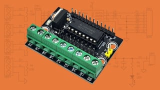
Whether you go with arduino, RPi, or MacBook. It emulates the speed pot (what you were calling a rheostat in post #1, it's a Potentiometer AKA Pot AKA speed pot, not a rheostat) on your handlebar. You can control it from your program and it will send a signal to your speed controller that will be indistinguishable from a twist of the throttle to the golf cart.
Lots of great information here, and you seem to be the person putting it in a language we newbies to the site can understand. I'm looking to do the same thing but just have a remote control that allows me to start the cart set the speed then stop it. I know I'm asking for a pretty simple thing but at which point in this feed should I go back to? Or do you have a quick simple answer. Thanks everyone!
 
Top