Relay diode suppression for Raspberry Pi - single diode not enough, what next?

Thread Starter

nanok66

Joined Jul 14, 2016
75
Hi all,

I have a large machine (keg washer) controlled by a Raspberry Pi (actually the Pi Compute 3+ with IO Module). I was previously having issues with my power relays (24VDC coil) that control high amperage 220V power accidentally triggering some of my Pi's GPIO push button inputs.

I added diodes across the relay coils and it pretty much solved the issue. Diodes were 30V 1500W (mouser link)

But I've been testing the machine more than ever recently and unfortunately the false input trigger issue happened again. I've been testing it a few times more today and could not get it to repeat so apparently the issue is rare - but I really don't want to settle for rare. I'd prefer to fully solve this issue.

So my question is if I am already using diodes to suppress the relay coil spike, what could be a reasonable second line of defense?

One thing I might add is I recently switched from using the Pi's internal pulldowns on my push button (which I think are 20K) to using external pull downs at 10K. The issue hasn't happened since but I am not convinced the stronger pull down actually fixed it.

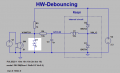
I attached a schematic to show exactly how the Pi activates the relays.

Component links:
MOSFET (3.3V logic level)
IDEC RELAY (intermediate relay, the datasheet says it has surge suppression circuit)
POWER RELAY (does not have surge protection but I added diode)

pi gpio inout.jpg
 

Thread Starter

nanok66

Joined Jul 14, 2016
75
Also if you were wondering yes all these components are in the same box. The relays are definitely on the other side of the box compared to the Pi (closest edge distance is about 4 inches). I have been thinking of putting the Pi in some small metal case. Not sure if that's the issue tho.
 

ericgibbs

Joined Jan 29, 2010
18,766
One thing I might add is I recently switched from using the Pi's internal pulldowns on my push button (which I think are 20K) to using external pull downs at 10K. The issue hasn't happened since but I am not convinced the stronger pull down actually fixed it.
hi nano,
This could indicate that push button switch bounce could be a problem, try adding a simple R/C filter on the push switch.
E

Look here:
https://www.allaboutcircuits.com/technical-articles/switch-bounce-how-to-deal-with-it/
 

Irving

Joined Jan 30, 2016
3,843
If you are switching high voltage/high current AC to the motor you are getting arcing at the power relay contacts. Although it is quenched within 10mS as the AC goes through 0v there is potentially a large energy spike which can be induced into your system. This will be especially true if your grounding has loops. All of your low voltage grounds need to be wired star-like back to a single point which ideally should be connected to the mains protective earth. Otherwise what you think is ground on your switch could easily bounce a volt or so above ground, giving a false input. Some input filtering as suggested above might help as well but won't solve all of that, false triggers will still randomly occur when a combination of circumstances is right.

If it's not possible to star wire the grounds, try to ensure that switch ground and the switch wire are twisted together and are as short as possible so any induced voltage is low and the same on both, reducing the likelihood of a sufficient difference between them to give a false trigger.

Edit: if you're running 3.3v to the switch that's a ground equivalent. All the above applies, but you should decouple the 3.3v to ground at the switch panel with a 100nF capacitor. Personally, in this environment I'd want my switches ground referenced with a pull-up at the Pi end and reverse the logic in software.
 
Last edited:

Irving

Joined Jan 30, 2016
3,843
I have been thinking of putting the Pi in some small metal case. Not sure if that's the issue tho.
Probably won't help as the EMI is in the switch and/or power supply wiring.

Another thing you could try is a snubber capacitor/resistor in series across the power relay switch contacts.
 

Deleted member 115935

Joined Dec 31, 1969
0
The sort of problems you are showing, are a real pain int the B**T,
This is not going to help , but the only way IMHO is to design from the beginning for resisliance.

so yes, diodes across relay coils are mandatory, I not you have only put a diode across one of the coils , you need to do both.

The Rasp Pi power, where does that come from ? does that glitch when the heavy motor starts / stops ?
you need to ensure the pi has clean power,

Separate earth / power return for the relays , motors , Pi are essential.

look at your code,
You need to make that resiliant also,
any input, you need to "debounce" and sanity check. So if you get a 10 ns pulse it is not mistaken for a button press of many 100 of milli seconds.

Keep the signal wires away from the power wires,

Your 10 K pull down resistor is doing nothing, Its to high a value to pull down a logic input,

the normal way to wire a switch in , is the switch goes to earth, and then you use a pull on the digital input.
that way, you dont need a pull down resistor, and the pull up on the logic input is helping you.
 

sagor

Joined Mar 10, 2019
903
Your IDEC relay should have a suppressing diode across its coil (don't trust the datasheet, their suppressor may not be sufficient). Also, instead of a transient suppressor on the coil with 220V, put a standard 1N400x series across the coil. Transient suppressors are not quite the same as standard diodes like the 1N4007 types
 

KeithWalker

Joined Jul 10, 2017
3,063
Snubbers should help a lot. They will limit arcing on the relay contacts so you should get much less interference. They will increase the life of the contacts too.
Keith
 

Thread Starter

nanok66

Joined Jul 14, 2016
75
Thanks everybody for the responses. Ok got a few questions tho.

@Irving When you are talking about grounds I think you started talking about AC grounds, but the push button input is of course DC and pulled down to DC ground so I'm a little confused on when you said "low voltage grounds" should be connected to earth, you mean all AC grounds right?

Just to make it clear I have AC grounds from (2) 220V devices and (1) from the 110V DC power supply, so all those 3 AC grounds are all star connected, and connected to the machine chassis.

As for DC grounds (0V) they are all star connected to one area on a PCB and that PCB area goes back to my DC dual power supply 0V.

The DC power supply is a Delta dual power supply 24V/5V (mouser link here). So @andrewmm I think the power is clean, it's a nice power supply, and no I don't notice any strange effects other than my rare false input when the motor turns on. I definitely like your idea of software debouncing any 10ns pulses, perhaps I'll try that. And yeah lol even after all the work of coding, wiring, PCB, etc.. these final issues are so strange and mysterious to solve...

Yes to everyone who suggested I can easily reverse my input wiring and ground reference my push button switches (the Pi has internal pull ups too).

Also @KeithWalker and @Irving can I use both snubber RC circuit AND a diode? Or do I need to choose one or the other?
 

Irving

Joined Jan 30, 2016
3,843
Hi,
I was referring primarily to DC grounds but it sounds like you've already star-wired them.

The snubber network is, across you motor power relay contacts while the diode is on your first 24v relay coil. So both, but the snubber probably the more useful.
 

Ian0

Joined Aug 7, 2020
9,667
Firstly, your suppression diode is on the wrong relay. The real problem is on the coil switched by the MOSFET. When you say “30V 1500W diode“, I assume you’re using a transorb. What you need is just an ordinary diode. Something slower than the MOSFET may be an advantage as well, if you have several relays, the old-as-the-hills ULN2003 is great, and it has the diodes built in. Don’t forget a decoupling capacitor between relay+ and 0V, 1uF ceramic is good.

Next, the pulldown resistor.
The raspberry pi has built-in pull-up resistors. Make sure you have switched them off, or your pull-down resistor will make things worse not better, by reducing the margin.
Better still to connect the switch to 0V and have a pull-up resistor. Then reduce the pull-up to 1k, and put 1uF across it, and add some resistance (about 100 ohms) in series with the switch to prevent the current into the capacitor eroding the switch contacts.
That should fix it.

can I suggest using a 230V AC coil contactor to switch the load, and switching the coil with a triac/opto-triac circuit. I switch three-phase at 100kVA with no trouble that way.
 

Ian0

Joined Aug 7, 2020
9,667
I’d suggest ditching the first relay. Drive the second one with the MOSFET. What’s the first one doing apart from generating extra interference on your supply? The second is being switched by the contact bounce from the first, so you don’t have just one spike on the supply, you have one for each time the contacts bounce.
100ohm Resistor in series with the switch is important, and you could make that 100n bigger if the problem doesn’t go away.
Have you though about digitally filtering the signal from the switch? In simplest terms sample it every quarter of a second or so, and ignore it unless you read four zeros in a row.
 

kandilar

Joined Mar 10, 2018
7
A few suggestions;
- First, as sagor said, you must absolutely put a 1N4007 type diode accross the first relay (actualy both relays).
1.5KE30A is ESD protector not a reverse voltage protector. In addition, clamping voltage of 1.5KE30A is around 50V!, which is too high. Generally relay coils generate voltages higher than the double voltage feeding it.
- Afterwards, I think you must test your system without connecting the heavy 220V load to see if the problem continues.
 

gernot

Joined Jul 18, 2016
3
C1 is a ESD protection device. It's not recommend to use the capacitor for debounce the switch, but it's a good idea to use a serial resistor of e.g. 100 Ohm for filtering rf). The switch should be debounced with a software filter as you noted.
 

Ian0

Joined Aug 7, 2020
9,667
C1 is a ESD protection device. It's not recommend to use the it for debounce the switch. The switch should be debounced with a software filter as you noted.
Nonsense. R/C filter (With two resistors as I previously said) is exactly how you debounce a switch. C1 is a filter capacitor. If I needed ESD protection I’d need a zener.
 

Baker Steve

Joined Feb 21, 2016
16
No way I'm an expert, but I did once work on an electromagnetic compatibility unit. Could you not do away with all the problems, the MOSFET and both relays using an opto-coupled triac to do the mains switching? Assuming you can get one that will handle the power you need to switch.

Just a though, please on-one jump on me:)
 

Ian0

Joined Aug 7, 2020
9,667
No way I'm an expert, but I did once work on an electromagnetic compatibility unit. Could you not do away with all the problems, the MOSFET and both relays using an opto-coupled triac to do the mains switching? Assuming you can get one that will handle the power you need to switch.

Just a though, please on-one jump on me:)
See post #12!
Though for *really* big loads, I’d use the triac to switch a contactor.
I’ve switched 100kW using that method.
The triac would get a tad warm - dissipating 1 Watt for each amp of load current.
 

gernot

Joined Jul 18, 2016
3
If you think so ... :-O
Why use a high value capacitor for debouncing, if you have microcontroller and can filter out the glitches? But if you are not familiar with programming, of course you can solve this problem with hardware. But then you should use also a higher resistor value.

hw-debouncing_sig.png

And of course the serial resistor and capacitor works for rf, since it's a low pass. For high energy esd pulses it's recommend to use a TVS and not a zener.

For low energy ESD pulses a capacitor instead a TVS diode eats the ESD energy.
 

Attachments

Top