 Facebook
 Google
 GitHub
 Linkedin
Hey there, AAC,
Long-time reader, first-time poster.
(Mr. Obvious, Bob and Tom... almost)
Me:
Questions:
Context:
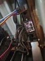
Photos are included below/attached for context and to better inform the question.
Additional technical details (to remove assumptions):
I should also mention that the job is complete except for the wiring of pins 86 and 87a. Therefore, mass rework is... undesirable... but feasible if necessary. I didn't want to cycle the relay until I installed sufficient protection to the truck itself.
Thanks, again, to those who assist.
WA_DIYer
Long-time reader, first-time poster.
(Mr. Obvious, Bob and Tom... almost)
Me:
- I am an engineer (not electrical) that prefers to DIY things I haven't before. It's fun, and has conditioned me to ask before I step in a direction where there may be a crevasse I must then crawl out of. I'll do it, but I prefer to step over them instead. Considering the consequences of a damaged parent circuit in this case, I think it is best to ask now. It is also a nuanced question (to me).
Questions:
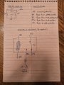
- A. Where do I place a diode in my circuit to protect the rest of it from the voltage spikes caused by a relay cycling? Yes, around the coil, but which specific pins? Pins 85 and 86 alone (see diagram below)?
- B. Is enhanced protection provided by installing multiple diodes to protect upstream and downstream? Alternatively, is only one (asked above in A.) necessary?
- C. To confirm, the grey line on the diode indicates the cathode, which should be connected to the power supply side, correct?
Context:
- I am looking to add step lighting to a Ford Super Duty.
- The truck as existing, integrated upfitter switches. I want to use one of these switches to provide on-demand additional light outside the truck (condition 1/2).
- The step lighting shall also turn on when the parking (e.g., a door opens, the unlock button is pressed, etc.) lights illuminate (condition 2/2). These lights and parent circuitry are already installed at the manufacturer, but will provide a signal to power the lights when the relay is not triggered (i.e., providing power under normally-closed positioning).
- The step lighting is managed by an LED controller installed under the chassis.
Photos are included below/attached for context and to better inform the question.
Additional technical details (to remove assumptions):
- Truck upfitter switch is a 12V 25A circuit. This corresponds to pin 86.
- Truck battery is standard 12V power supply. This corresponds to pin 87a.
- LED controller is this model: https://luxlightingsystems.com/products/rgb-controller-bluetooth-single-zone
- 5-pin relay is this unit: https://www.amazon.com/PACK-AMP-Wat...-1-spons&sp_csd=d2lkZ2V0TmFtZT1zcF9hdGY&psc=1
- Note: the diagram shows an integrated resistor, but the technical specs do not state the protection it affords. I have not read having both conflicts in any way, thus, I would like to add the diode if I can learn where to appropriately do so.
- The vehicle parking light signal is providing the power (+) for pin 87 in the diagram. I am using the integrated ground (factory installed as a two-wire pull) to serve as the ground for the relay and the controller. This was located under the driver side sill plate cap. I soldered a watertight connector and then rerouted it through a watertight rubber gromet to the control location.
- All cabling connections are completed using soldered, watertight butt connectors with shrink wrap added overtop. The routing then follows factory installed cable paths and trays and are secured with zip ties.
- Intended 1N4004 diode(s) (procured but not installed) are this model: https://www.amazon.com/BOJACK-Recti...-1-spons&sp_csd=d2lkZ2V0TmFtZT1zcF9hdGY&psc=1
I should also mention that the job is complete except for the wiring of pins 86 and 87a. Therefore, mass rework is... undesirable... but feasible if necessary. I didn't want to cycle the relay until I installed sufficient protection to the truck itself.
Thanks, again, to those who assist.
WA_DIYer
Attachments
-
 2.1 MB Views: 21
 -
 2.7 MB Views: 24


