Reducing Ringtime in Ultrasonic Sensing Circuit

Thread Starter

Daniel McMath

Joined Dec 28, 2015
50
I'm working on an ultrasonic ranging system. I've gotten some help from the members of this forum in the past to help clean up some signal issues, and to add some bypasses to clean up the power a little. Given that I'm not a EE, any help I get is deeply appreciated. Honestly, I'm just a dude with a soldering iron, an account at Mouser, and too much time on my hands.

So the question: How do I reduce the ring time? See the attached o-scope reading -- this is a pretty clean signal, as signals go, showing a solid ring from the initial transmit, then a good response ping a moment later. The trick is that if the target is too close, the response gets buried in the ring, and I can't detect it.

Clean Signal GSM60B (2).jpg

And the other question, which is like the first: Is there any way to clean up the signal a bit? Can I reduce the ring while improving the strength of the return, at the same time?

Schematic 5d(2).png

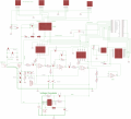
I've attached a complete circuit diagram (minus the voltage regulator, which is pretty straightforward).
- Power comes in on the left; supplies the amplifier.
- Amplifier / filter circuit lives in the middle. Nominally, it's a band pass filter that allows 40kHz to get through, while amplifying that 40kHz in the process.
- The headers on the right interface to the Arduino board to provide control to the multiplexer, and to provide a signal to the MOSFET that drives a "ping" signal.
- The headers across the top of the board go out to 4 sensing elements. Note that I've added a ground-filter to the return-side ground, which seemed to clean up the signal a bit, at the expense of a little overall amplitude.
- Switching MUX channels causes some noise on the line, but it fades pretty quick; because it's a single activity, it only cycles the transmit piezo element for an instant, so I can wait for 2ms before transmitting the ping, and there's little or no ill-effects from the switching transient.

... So any thoughts? Are there obvious ways that I can improve on this?

Thanks again for the help, all. :)

Dan
 

Thread Starter

Daniel McMath

Joined Dec 28, 2015
50
MrChips, the real question is "How close *can* I measure?" Or, more accurately, "Can I measure closer than I am?" :)

Right now, I can pick out a return from the ring within about 800usec, though not always consistently. Sometimes it's got to be 1000usec away before I can consistently get good returns. I've engineered the living daylights out of the transmit/receive assembly to minimize the mechanical coupling between the transducers, and I'm using the best quality piezo transducers I can find (notably, the $0.80 made-in-China ones demonstrate much worse ring than the $15 sensors). So now I'm down to seeking better signal by improving the circuit. Can I get down to 600usec? 400? I guess what I'm really asking is: Is there something I'm doing wrong in my circuit that's causing more ring than I should be getting?

Danadak -- thanks for the google; my circuit is actually closely related to the circuit from your first link. It's quite likely that I referenced that document in my design.
 

ericgibbs

Joined Jan 29, 2010
18,843
And the other question, which is like the first: Is there any way to clean up the signal a bit? Can I reduce the ring while improving the strength of the return, at the same time?
hi,
Most commercial sounders use TGC, Timed Gain Control, the gain of the Receiver increases with respect to the TX time.
E
EDIT:
Have you confirmed that the TX and RX are matched at their resonant frequency.?
Your posted waveform suggest that they are not.
 

Thread Starter

Daniel McMath

Joined Dec 28, 2015
50
hi,
Most commercial sounders use TGC, Timed Gain Control, the gain of the Receiver increases with respect to the TX time.
E
EDIT:
Have you confirmed that the TX and RX are matched at their resonant frequency.?
Your posted waveform suggest that they are not.

TGC sounds like a very cool idea. I'm thinking an implementation would have stages in the amplifier that change resistance over time? As a guy who isn't a EE, I'm thinking that the complexity involved would be fairly high -- in this amplifier, gain elements are tied to filter elements, and it's all tuned. So changing a resistor would modify the frequency of a filter element, unless I also changed the capacitance at the same time. ... Unless I had a separate amplifier stage that was dedicated just to amplifying, not filtering...

...FYI, I ended up using a different solution for that problem. I didn't know how to solve it in the circuit, so I ended up solving it in code. I use an ADC to sample the return, then process the ping response in software. I can almost guarantee it was more effort than a good EE would have put into a TGC solution, but I'm a software guy more than a hardware guy, so it worked well for me. :)

Re TX/RX resonant frequency matching ... forgive my ignorance here, what would that look like? I'm using identical transducers for TX and RX. The TX signal is calibrated as closely as I can get it to the published resonant frequency of the transducer (40kHz). I put in a couple of inductors in the transmit line, which I found gave me a little resonant boost in the TX signal (L1 and L2 in the drawing above). The RX circuit should be tuned pretty close to 40kHz.

So now I'm wondering all kinds of things:
- What resonant optimization did I miss? If there's some straightforward way to match TX and RX resonance more closely, I'm very interested.
- How can you tell, just looking at the trace, that it's not matched? What's the "tell?"
- Some circuit tweaks that I added that weren't really textbook were the transmit inductors (R14/L1/L2, just below the MUX) and the return ground filter (C12/R17, off on the left side of the drawing). Am I completely off base with those things?

Thanks,
Dan
 

RichardO

Joined May 4, 2013
2,270
Some thoughts come to mind...

Make sure that there is nothing around the transducer to cause an early echo. For instance a wall or part or your enclosure.

Make sure that the transducer is acoustically isolated from its mounting. The mounting might be vibrating when the transducer is pulsed.

Raising the lower frequency cutoff of the amplifier might help get rid of that large squarish first echo. The danger is that this might also reduce the amplitude of the echos.

By using a higher frequency transducer you might be able to decrease the time the transducer rings.

As mentioned earlier you can control the gain as a function of time. The extreme of this is to disable (blank) the receiver completely for a short while right after the transmit.


I have attached information on how it was done in old Polaroid cameras.


edit: Added data sheets for the IC's used on the SN28827 ranging module.
 

Attachments

Last edited:

ericgibbs

Joined Jan 29, 2010
18,843
- How can you tell, just looking at the trace, that it's not matched? What's the "tell?
hi DM,
There is a modulation 'beat' pattern in the echo signals.
Do the inductors have tuning slugs.?

One method for reducing the effect of the transmission pulse, is by having a Suppression period on the receiver input.
Based on your images I would say a 0.3mSec Suppression period would be OK.
After the suppression period, time increase the gain of the receiver.

E
 

Thread Starter

Daniel McMath

Joined Dec 28, 2015
50
Some thoughts come to mind...

Make sure that there is nothing around the transducer to cause an early echo. For instance a wall or part or your enclosure.

Make sure that the transducer is acoustically isolated from its mounting. The mounting might be vibrating when the transducer is pulsed.
Good call; I spent a long time working through mechanical isolations on the transducer end of the problem. I've ended up using the most expensive transducers I could find, mounted in exactly the right rubber, with just the right setup to keep pressure in the tank. This is for a tank level indication system, so there's not much I can do about walls or nearby enclosure bits.

I have attached information on how it was done in old Polaroid cameras.


edit: Added data sheets for the IC's used on the SN28827 ranging module.
Wow, that's a pile of gold. Thanks for sharing those. I'm not sure I'm smart enough to implement any of that, but it's some great ideas.

Thanks,
Dan
 

Thread Starter

Daniel McMath

Joined Dec 28, 2015
50
hi DM,
There is a modulation 'beat' pattern in the echo signals.
Do the inductors have tuning slugs.?
No, the inductors are just basic fixed inductors. I did some math to try to pair the capacitance of the transducer with an inductive element, in hopes of getting a little resonant amplification. If memory serves, I did see some gains after implementing this. The values of the inductors were at least partially based on what was available and affordable; I think the math called for something with a little different value, but those were unobtainable.

Am I totally off the mark with the inductors? Do I need to use tunable inductors, and hand-tune the board against an o-scope?

One method for reducing the effect of the transmission pulse, is by having a Suppression period on the receiver input.
Based on your images I would say a 0.3mSec Suppression period would be OK.
After the suppression period, time increase the gain of the receiver.

E
Yeah, I'm still pretty hazy on how to actually implement a time increase gain function. Also suppressing the amplifier. I mean, so I can suppress the amp, sure; I'd just wire the power lead (or the ground lead) to a transistor so I'd have an "enable" trigger. But when I enable the amplifier, wouldn't I just get a spike, causing just as much noise as I'm already getting? :confused: I think I have analog outputs, so I could ramp up the power to a transistor over the course of 0.3ms, which might minimize that spike?

Is there a straightforward way to do time adjusted gain? My only thought on how to do that, really, would be to swap out the existing gain resistors with digitally variable resistors, so I could use software to crank up the gain over time. I'm sure that's the hardest possible way to do that, though.
 

Thread Starter

Daniel McMath

Joined Dec 28, 2015
50
Alright, well ... that wasn't as bad as I thought it would be. I ended up writing a serial driver for the digital potentiometers, which I really didn't understand before I started, but now I've got time adjusted gain. Well, sort of. Right now, I've got one stage of time adjusted gain built on to the board, still working on the second. Still, I'm getting pretty good signal, and the adjustment of gain is actually working, even if not as well as I'd hoped.

Yeah, I know, I was shocked too. I mean, for a guy who's not an EE at all, I feel pretty good about this.

For those who are curious: updated schematic and current "ping" reading from o-scope attached. Thanks for the help, Mr. Gibbs.

Dan
 

Attachments

Top