Reducing 110VAC to power a very small coil on a relay

MisterBill2

Joined Jan 23, 2018
28,059
Less more information let's get the terms.
This is a typical Reed Switch Note the data sheet specifications as to current handling capability.
This is a typical Reed Relay The reed relay includes a coil and is named a reed relay.

They are not the same. Since you mention Reed Switch those wanting to help will need a data sheet similar to what I linked to.

Also since you mention a 110 VAC 10 Amp load you will need switching at least 20% greater than your max load. Using a simple reed switch magnetically turned On/Off I would apply a low voltage like maybe 12 VDC to your reed switch. I would use an AC SSR with a 3 to 32 volt DC control voltage. Let the reed relay drive the SSR. I can only guess you want to maybe use a low voltage DC to switch a 110 Volt 10 Amp AC load.

Consider also if you were to use a reed relay that if you apply AC to a Reed Relay coil it will be switching at the AC frequency applied.

Typical inexpensive AC SSR using a low DC control voltage. I can't speak for the quality of these imported SSRs, personally I used brands like Omron and other more expensive versions. In closing this will not be as simple as using a few resistors.

Ron
Omron is indeed another good brand. Crydom was specified for production equipment by one of the auto companies we buit machines for. So based on that, and that we never had any failures, I recommended them.
 

Reloadron

Joined Jan 15, 2015
7,908
Omron, Crydom, Gordos and the list goes on. They all come with a price tag. While Omega markets them I am pretty sure Omega doesn't manufacture them. The units pouring off the boat I have no clue. Seldom do we see a thread starter mention a budget making a bill of materials impossible. Once we know exactly the thread starters game plan we can offer up better help and suggestions. My own designs were restricted to using higher end parts. Deep pockets were part of everything. :) Making something for home or hobby use offers much more flexibility.

Ron
 

DickCappels

Joined Aug 21, 2008
10,662
Does this mean Mains topics are no longer off limits or out of bounds?
Yes, the change in the User Agreement is years old. "Mains topics" were never out of bounds - remember we have helped people with off-line switching supplies for many years. Along the lines of Mains connected circuit it was just the transformerless power supplies and LEDs to the Mains that were taboo until this last change.
 

MisterBill2

Joined Jan 23, 2018
28,059
I would still be concerned because it is clear to me that some of the folks posting here have no clues at all. So perhaps a compromise, such as adding a "Hazardous Voltage" warning would be in order.
 

ericgibbs

Joined Jan 29, 2010
21,538
Hi.
The Forum Rules, T&C's are defined well enough for Admin and the Moderation team to take the necessary action on a case by case basis regarding the electrical safety of a possible inexperienced poster.

If you have a concern, about a particular Thread, submit a Report explaining your reason for concern, Admin/Moderation will take the appropriate action.

Mod.
 

Reloadron

Joined Jan 15, 2015
7,908
If you have a concern, about a particular Thread, submit a Report explaining your reason for concern, Admin/Moderation will take the appropriate action.
With that in mind can we focus on the thread? Should anyone feel the thread violates any forum rules Eric points the direction to take. It's very easy to report a thread and question moderation using the Report button. It's also very simple to question a thread in the feedback section. I just expressed my opinion there. I now return you to our regularly scheduled programming. :)

Ron
 

ThePanMan

Joined Mar 13, 2020
950
More than just reading the T&C and Community guidelines once, I suppose I need to review them periodically. Perhaps an email would have alerted me (and others) when changes to the rules occur.

Nevertheless, back on topic: We still don't (or I don't) know enough about what the TS wants to achieve. And for the sake of clarity, TS stands for Thread Starter, i.e. the person who posted the question. Though I've seen it done I'm not in favor of capacitive voltage dropping. Not sure why I'm skittish about it - but suffice is to say I am skittish when it comes to messing with potential line voltages. I've had enough shocks to hold me over for the next two or three reincarnations. Though I don't really believe in such, and no, let's not digress into another topic.

Until we know more about what materials and plans the TS has it's not practical for me to give advice concerning methods of achieving the TS goal.
 

MisterBill2

Joined Jan 23, 2018
28,059
More than just reading the T&C and Community guidelines once, I suppose I need to review them periodically. Perhaps an email would have alerted me (and others) when changes to the rules occur.

Nevertheless, back on topic: We still don't (or I don't) know enough about what the TS wants to achieve. And for the sake of clarity, TS stands for Thread Starter, i.e. the person who posted the question. Though I've seen it done I'm not in favor of capacitive voltage dropping. Not sure why I'm skittish about it - but suffice is to say I am skittish when it comes to messing with potential line voltages. I've had enough shocks to hold me over for the next two or three reincarnations. Though I don't really believe in such, and no, let's not digress into another topic.

Until we know more about what materials and plans the TS has it's not practical for me to give advice concerning methods of achieving the TS goal.
The flaw of capacitive voltage dropping is that the calculations are based on a perfect sine wave, with no harmonic content, or other distortion. Thus any higher frequency will result in a much higher voltage being delivered to the load.
There may be additional flaws, also, but that one flaw can certainly be a show-stopper.
This is why one must not try to use a "Kill-a-Watt" meter with an emergency backup generator.
And consider that many switcher power supplies generate harmonic distortion in the mains connection, capacitive dropping is a poor choice. So now PM can know the quite vaid reason for the concern.
 

Thread Starter

mjscott

Joined May 21, 2014
24
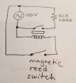
The volume of comments is very appreciated!!! I am just a hobbyist, and I apologize for my lack of experience in using the correct terms to explain my project, thus causing some confusion. Below is a sketch which might help explain what I am trying to do. The top portion of the circuit is my power supply (110vac), my 10A load, and the relay which switches it on. At the bottom of the circuit is the magnetic reed switch I wish to use to activate the relay (and send power to my load). The snag is that the reed switch is only rated for 0.5A max. Obviously if I built the circuit as I've draw it, the reed switch would go POOF with a bang and puff of smoke. My desire is to utilize the existing power source and reduce it to a safe level for the reed switch. I'm working in a very tight space and would like to avoid a transformer (wall wart) to reduce the voltage. This is why I thought a resistor(s) connected at the reed switch might do the trick. I have not purchased the relay yet so I don't have specs on the coil. I was waiting to learn some more from this thread before committing to parts. Finally, cost is a factor. I need to build 20 of these. I can purchase a commercial product that does exactly what I want, but the cost is $80/ea. I'm hoping I can 'roll my own' for considerably less.
With thanks
Mike


20220304_124434.jpg
 

Reloadron

Joined Jan 15, 2015
7,908
This is why one must not try to use a "Kill-a-Watt" meter with an emergency backup generator.
I have used a Kill-A-Watt meter with several backup generators and they do just fine. While I have not used inductive loads I have used calibrated resistive loads and not seen any difference between my residential AC mains supply and backup generator. This includes my first old beater Coleman 5.0 KW surge and 4.0 KW run generator powered by a Briggs and Stratton 8.0 HP generator which actually puts out a pretty clean sine wave as well as my large backup generator. The forum has a pretty good article on THD. ELY the ICE man is in the link.
As to capacitive dividers and the forum? They are discouraged because there is no isolation betweens the mains voltage and load. They are not a "good idea" especially for a beginner so their use is discouraged. Well actually their use is a prohibited subject in forum discussion as a matter of general safety.

Ron
 

Reloadron

Joined Jan 15, 2015
7,908
The volume of comments is very appreciated!!! I am just a hobbyist, and I apologize for my lack of experience in using the correct terms to explain my project, thus causing some confusion. Below is a sketch which might help explain what I am trying to do. The top portion of the circuit is my power supply (110vac), my 10A load, and the relay which switches it on. At the bottom of the circuit is the magnetic reed switch I wish to use to activate the relay (and send power to my load). The snag is that the reed switch is only rated for 0.5A max. Obviously if I built the circuit as I've draw it, the reed switch would go POOF with a bang and puff of smoke. My desire is to utilize the existing power source and reduce it to a safe level for the reed switch. I'm working in a very tight space and would like to avoid a transformer (wall wart) to reduce the voltage. This is why I thought a resistor(s) connected at the reed switch might do the trick. I have not purchased the relay yet so I don't have specs on the coil. I was waiting to learn some more from this thread before committing to parts. Finally, cost is a factor. I need to build 20 of these. I can purchase a commercial product that does exactly what I want, but the cost is $80/ea. I'm hoping I can 'roll my own' for considerably less.
With thanks
Mike


View attachment 262107
Just keep in mind your relay coil in your illustration can't draw current exceeding the reed switch. I gave links to reed switch examples earlier. Next your AC power should reflect a Neutral verse Line in your drawing. Your relay contacts must be able to handle the load plus an overhead of at least 20%. Personally I would run with an SCR and if you want 120 or 110 volt control just use an SCR designed for 110 volt control.

Ron
 

MisterBill2

Joined Jan 23, 2018
28,059
Thanks for giving us the circuit. Now a whole of of things are clear.The reed is only a switch, and the relay is a separate entity completely. The very good news is that there are a wide variety of reed switches, including some rated for 120 volts AC use. The item that would be large is a relay good for at least ten amps, 15 is a better choice here, that is not large. That is my other reason for suggesting an adequately rated solid state relay. the Omron And Crydom units I have used are about 1.5 inch by 2 inch by 3/4 inch thick, with easy to use screw terminals. I am not sure if those are availabe with 10 volt control inputs. You will need to check a catalog.
 

ThePanMan

Joined Mar 13, 2020
950
OK, the relay coil needs to be rated for 110VAC. The relay contacts need to be rated for at least 15 amps AC. The magnetic reed switch needs to be rated big enough to handle both 110VAC AND the amount of current the relay will draw. If the relay coil draws 0.5A then a 0.5A (AC rated) reed switch will do.

Thanks for the clarity.

Assuming your relay coil is rated for 110VAC and an inductance (resistance) of 220Ω then the relay will draw 0.5A. As for the load, it's controlled via the relay contacts which should be rated higher than the expected RESISTIVE load. There IS a difference between resistive and inductive loads.

So now a new question: What is your "Load"?
 

Reloadron

Joined Jan 15, 2015
7,908
Well then just about any relay with 10 Amp AC rated contacts will do. Originally you defined a 10 Amp AC load. Thus you get suggestions of contacts rated at 15 amps allowing for overhead. If you want a mechanical relay Omron makes good solutions Just off the top an Omron MK series general purpose relay will do just fine. With a 50 or 60 Hz coil the coil current shouldn't exceed 60 mA which is fine. The simple DPDT versions come with an octal base requiring a socket.

Since I have no clue where you are located I really can't suggest where to buy. Here in the US either Grainger Supply or McMaster Supply both are industrial supply parts houses. Here is an example of a whole page of relays from McMaster Carr supply. These are basic off the shelf flavors. You want 7071K13 or 7170K21 the difference is one has a LED indicator when the relay is powered. You need the socket indicated with the relay.

Ron
 

MisterBill2

Joined Jan 23, 2018
28,059
Well then just about any relay with 10 Amp AC rated contacts will do. Originally you defined a 10 Amp AC load. Thus you get suggestions of contacts rated at 15 amps allowing for overhead. If you want a mechanical relay Omron makes good solutions Just off the top an Omron MK series general purpose relay will do just fine. With a 50 or 60 Hz coil the coil current shouldn't exceed 60 mA which is fine. The simple DPDT versions come with an octal base requiring a socket.

Since I have no clue where you are located I really can't suggest where to buy. Here in the US either Grainger Supply or McMaster Supply both are industrial supply parts houses. Here is an example of a whole page of relays from McMaster Carr supply. These are basic off the shelf flavors. You want 7071K13 or 7170K21 the difference is one has a LED indicator when the relay is powered. You need the socket indicated with the relay.

Ron
I suggest looking for the same relays at an electronic supplier ike Aide, newark, Avnet, or Digikey. The price should be less.
 

Reloadron

Joined Jan 15, 2015
7,908
I suggest looking for the same relays at an electronic supplier ike Aide, newark, Avnet, or Digikey. The price should be less.
I agree but as usual I have no clue where the thread starter is? The 110 volt might point to North America but not knowing where they are males it difficult to source a part. I gave a few examples and they can go shop wherever trips their trigger. Newark, Allied and there are dozens of distributors to choose from.

Ron
 

Thread Starter

mjscott

Joined May 21, 2014
24
I agree but as usual I have no clue where the thread starter is? The 110 volt might point to North America but not knowing where they are males it difficult to source a part. I gave a few examples and they can go shop wherever trips their trigger. Newark, Allied and there are dozens of distributors to choose from.

Ron
Yes, North America - Canada west coast to be specific :) Sourcing parts is no problem, thanks to the Internet. I get most of my stuff from Digi-Key or the local electronics shop ( Interior Electronics ).
 

Reloadron

Joined Jan 15, 2015
7,908
Yes, North America - Canada west coast to be specific :) Sourcing parts is no problem, thanks to the Internet. I get most of my stuff from Digi-Key or the local electronics shop ( Interior Electronics ).
Wish I had a local place, they are all gone. Internet is about it and Digi Key and a few others. During my work years I used Allied Electronics quite a bit. For some stuff general plant in a hurry McMaster Carr was a GoTo since my department head drove past their local warehouse if they had it he would pick it up. Worked out well. I also had my stash of spare parts for stuff I designed.

Ron
 
Top