MisterBill2
- Joined Jan 23, 2018
- 28,552
I TOTALLY understood that this was strictly a battery powered tester! What I had not gotten was the idea of not adding any more parts, such as push buttons.
Hello Mister Bill2,I TOTALLY understood that this was strictly a battery powered tester! What I had not gotten was the idea of not adding any more parts, such as push buttons.

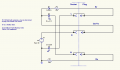
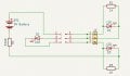
Hello AlexTHow about this ? :-
View attachment 366457
If all plug wires are correct, both LEDs light. If any wires are swapped, both LEDs are off.
The circuit can be powered by 2 AA cells and will work down to about 2.8V.
With the resistor values shown the current per LED is about 2.4mA.
If plug and socket are disconnected, current draw is zero.

My post #23 circuit would catch a short between L and N: neither LED would light. However, it wouldn't catch a LE short or NE short reliably.examples of problems that none of the other testers would catch:


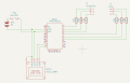
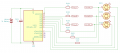
Hello Irving,@panic mode 'borrowed' my idea for a MCU based solution.. here's what I drew yesterday but didn't get a chance to post.
View attachment 366500
I've gone for an ATtiny84 because they are cheap and easy to program and the RP4020 is overkill - that's like using a Ferrari to mow the lawn. The idea is the MCU powers up and builds the truth table of plug to socket connections. if nothing found it goes into sleep mode until one of the inputs changes state or every, say, 5 seconds. If a Plug to Socket connection is found and the truth table is correct (1 of 81? possible matrices) the 3 LEDs light up green. If incorrect the LEDs are lit green or red as appropriate. There is scope for some fun 'light shows' with the LEDs before settling on the final result. Once the Plug is removed the MCU goes into sleep mode consuming 0.1ua typically. Normal run current is around 80uA using the slowest internal clock plus the LED currents (limited to 5mA approx per LED).
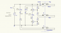
a Falstad simulation : https://is.gd/jSCFsb<LED-s and Resistors>
No problem. Will PM you a shopping list based on my setup (and the one my 12y old granddaughter uses!).Hello Irving,
Many thanks for the circuit. I have not done any MCU programming before but think it is about time I tried it so I will go with your design. I would be very grateful if you could give me a list of what I need to be able to program the ATtiny85. I can see other opportunities to use an MCU for other projects so should be able to justify the cost as an investment.
Thank you, Irving!No problem. Will PM you a shopping list based on my setup (and the one my 12y old granddaughter uses!).
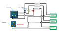
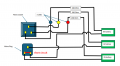
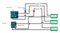
Here you go then, although I realise you have chosen the digital route :-I would like to have an individual LED for each of the three cables.

| Thread starter | Similar threads | Forum | Replies | Date |
|---|---|---|---|---|
|
|
MCU control of 100v to a number of outputs | General Electronics Chat | 16 |

| Similar threads |
|---|
| MCU control of 100v to a number of outputs |