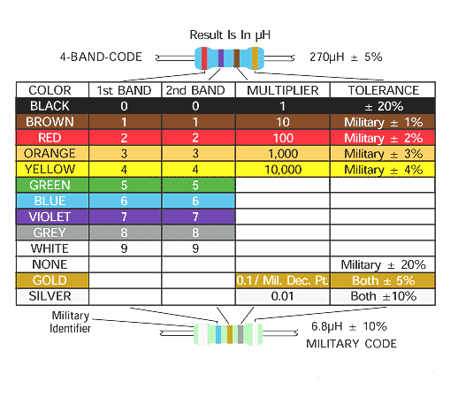
red, red, silver, gold - resistor or inductor or ?

Thread Starter

reapairman

Joined Dec 27, 2011
17
it's blue with red, red, silver, gold and looks just like a normal resistor.

i'd have thought it was .22 ohms or a temperature variable resistor, but it measures .5ohms, ignoring .1 meter leads resistance and doesn't change value even at 300 degrees c.

it's on the return from a BLDC 60 ohm motor winding via n-channel mosfet (1.5 ohm d-s) source pin.

just want to make sure it's not meant to be another value and the resistor has failed.

you can see it in the top right of this pic
 

THE_RB

Joined Feb 11, 2008
5,438
The value is uH on small inductors so it might be a 0.22uH inductor.

It's also possible it is a common fusible resistor 0.22 ohms. They can rise in value, especially if a high current fault has occurred.

The photo is not that clear but if it looks the same package as other resistors on the PCB it is likely a resistor. If its appearance is significantly different to the resistors it's likely an inductor.

It's not a particularly easy value inductor to test, and also 0.22uH is a very unusual value (and physical size) for an inductor in series with a PWM motor coil on a large motor like that.

I'm leaning towards resistor. Can you draw a schematic showing where it is in relation to the motor coil, FET and any snubbers?
 

Thread Starter

reapairman

Joined Dec 27, 2011
17
thanks for the replies,

excuse my bad handwriting. the 4 mosfets are all the same IRF830's and aligned the same way as the first one on the LEFT SDG from top to bottom.


thanks for looking
 

Thread Starter

reapairman

Joined Dec 27, 2011
17
also, a pic of the stator the plugs into the 2 connectors on the board. the 3rd connector on the stator (in the middle of the 4 coils) is unused.


THE_RB

Joined Feb 11, 2008
5,438
Looks like to connects between the source pins of the FETs to the ground (-ve) rail.

I would say its highly likely now to be a 0.22 ohm resistor, for current sensing, or even as a fusible resistor on the -ve supply rail (assuming the FETs are in halfbridges).
 

Thread Starter

reapairman

Joined Dec 27, 2011
17
thanks THE_RB, I wasn't sure.

I replaced all the mosfets with new ones, but the same 2 (on the right) shorted again, within a second of switching it on.

I guess for it to fail it must either exceed the DS current, GS voltage or DS voltage.

wonder if the IR2106 is blown and feeding it too much voltage at the gate

or if it's not turning on or off completely and then heating up too much.

need to blow up the circuit in photoshop and then overlay the other side of the board to connect up the vias and draw a proper schematic from that.
 

THE_RB

Joined Feb 11, 2008
5,438
The FETs should always run with PWM, if the driving circuit or sensors have failed and the FETs get turned on all the time they will blow very easily.

For testing you can use a reduced voltage and/or current limited PSU, which should keep the FETs alive even if they are turned on all the time. That can give you some time to check waveforms. Fortunately with a 3 phase motor there is something to compare the bad phase to.
 

Thread Starter

reapairman

Joined Dec 27, 2011
17
thanks again THE_RB, been desoldering and scratching away gloop to find hidden tracks and slowly deciphering the schematic and attempting to recreate it in eagle.

I've sketched a lot of it out on paper, but still need to draw it in eagle, but for now here is the power supply section, or most of it anyway.

I reckon the 2 mosfets that blew must have been the result of shoot-through, where 2 off them (wrong pair, either 1&2 or 3&4) were on, bypassing the motor.


in the diagram above, with mosfets 1 2 3 4 - they should be switched so that 2 and 3 are on and then 1 and 4 are on. repeat.

so the current goes from B+ -> diode -> mosfet 2 d-s -> motor coils -> mosfet 3 d-s -> .22ohm resistor -> B-

thinking it could be the IR2106S hi/lo mosfet driver, or the logic to the hi/lo inputs. it's coming via a hex inverting schmitt trigger, or a nand schmitt trigger chip, not sussed the whole thing yet tho.

I did spin the motor (very slowly) by using a 9v battery and alternating polarity to the 2 motor terminals. I'd like to build my own BLDC motor controller using an arduino as an experiment to see what kind of switching speed, PWM signal and hall sensor output I'd get. still studying the theory though.

I'm not 100% sure how to limit the voltage/current to the board, as you'll see from the part schematic I've made, it runs off 240v AC, which looks badly designed as the resistor droppers get really hot and burn the board. boiler engineers have reported the same resistors burnt on boards they have removed from relatively new fans.

I've got a selection of transformers and butchered ATX PS's but no proper bench PS or variac yet, I was thinking of using a lightbulb in series, to limit the current.

I really appreciate your help and input, cheers mate.

NOTE** that string of 4 330K resistors should actually be 4 82K resistors, totalling 328K


Last edited:

THE_RB

Joined Feb 11, 2008
5,438
Ouch that's nasty, running that little PCB and tiny FETs from 240v AC rectified and filtered, which is basically a high-current 350v DC supply! :eek:
 
Top