 Facebook
 Google
 GitHub
 Linkedin
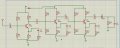
hello , i'm trying to do ASK modulation , i've generated a carrier using the circuit attached below , i'm getting a 16 MHz , 3 v p-p sine wave at the emitter , i want to make a simple receiver for my transmitter , i've tried cascading 3 CE amplifiers like in the 2nd attached schematic , but i'm getting no output , how can i design a receiver for this circuit any help is appreciated .
Attachments
-
 83.7 KB Views: 14
 -
 133 KB Views: 14


