I find this question a little vague. Do you know what v, z and x are supposed to represent? Are they fixed constants, or do they represent variable gains that must be independently controlled in a circuit? If they are variable, what controls them? Do they represent variable resistor controls?
I find this question a little vague. Do you know what v, z and x are supposed to represent? Are they fixed constants, or do they represent variable gains that must be independently controlled in a circuit? If they are variable, what controls them? Do they represent variable resistor controls?
Seems confusing to me. Maybe someone else has a more definite idea of what those functions mean. My best guess is that the are independent gain functions. An example could be a variable gain implemented by turning a variable resistor over an angular range. The angle is the independent variable, and the function, e.g. v(angle), is the gain that will result.
You would have to draw your circuit in a general way with resistor specified as gain factors times a fundamental resistor value. For example; resistors R and vR resistors can be used with an inverting opamp amplifier to give a gain of
Vout/Vin=-v
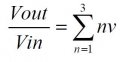
Your first formula amounts to multiplying by 6v, so you could use resistor values of R and 6vR on and inverting amplifier and follow this with another inverting amplifier with a gain of -1. The second circuit is more involved, but the same method can be used. For example an inverting summing amplifier combined with two inverting amplifiers - one on each of the inputs that need positive gain.
 Facebook
 Google
 GitHub
 Linkedin