Facebook
 Google
 GitHub
 Linkedin
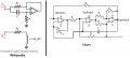
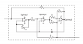
I tried to construct a Gyrator circuit (Figure shown below) to obtain a floating inductor. I used OPA445 to implement the circuit. After completing the circuit on the breadboard, I put a resistor (1KOhm) in series with the Inductor and measured the AC voltage across the resistor (to validate the Inductor). The voltage measured across the resistor didn't match the theoretical predictions, and the output pattern itself was erratic. By erratic I mean that there was no consistency in the error; With changing input frequency, sometimes the signal looked distorted, had a DC bias, and the amplitude didn't change.
I feel like I am missing something. Can someone point out what's wrong with this implementation?
Thanks,
Shiva
I feel like I am missing something. Can someone point out what's wrong with this implementation?
Thanks,
Shiva
Attachments
-
 7.7 MB Views: 45
 -
 20.8 KB Views: 48