Realizing 32 bit counter from 16 bit, SN74LV8154

Thread Starter

Smoooth

Joined Jan 2, 2017
34
Hi,

I'm using a dual 16 bit binary counter SN74LV8154-EP by Texas Instruments. I need to enable the 32 bit counter feature, and I'm having problems with that. And I'm also having weird outputs. I would really appreciate some help!

Please see an image of the circuit, as well as the data sheet for the counter attached.

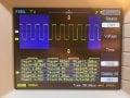
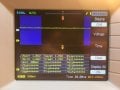
VCC for the counter is 3.04V. Input pulses are between 0.4V and 2.4V (20MHz oscillator). First I took Yn readings from counter A, and it works correctly except for the fact that output voltages are wrong. I'm supposed to be getting 0.48V for LOW and 2.48V for HIGH according to the data sheet, but I'm getting ~0V to ~1.8V. Why? That's my first question.

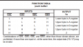
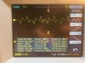
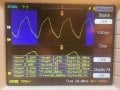
And I'm taking very strange Yn readings from counter B. 20MHz between -0.18V and 0.18V. The data sheet specifically states that "A 32 bit counter can be realized by connecting CLKA and CLKB together and by connecting RCOA to CLKBEN." I did that. Byte selection inputs are all correct too. It's not always LOW – I'm using a 20MHz oscillator, I'm supposed to observe some pulses. But for some reason it doesn't work. What am I doing wrong? And how do I solve it?

Thank you very much in advance!
 

Attachments

Last edited:

philba

Joined Aug 17, 2017
959
Are you trying to measure the outputs with a DMM when it's running? You will get weird readings, kind of like what you are seeing. Best use a scope or a logic analyzer. In the absence of that, can you feed the clock from a switch? Step it one count at a time and take measurements. You might have to debounce the switch or just live with the extra counts from the contact bounce.

By the way, we generally refer to the inputs and outputs as pulses - oscillations are more the analog domain. It took me a while to understand what you meant.
 

Thread Starter

Smoooth

Joined Jan 2, 2017
34
Are you trying to measure the outputs with a DMM when it's running? You will get weird readings, kind of like what you are seeing. Best use a scope or a logic analyzer. In the absence of that, can you feed the clock from a switch? Step it one count at a time and take measurements. You might have to debounce the switch or just live with the extra counts from the contact bounce.

By the way, we generally refer to the inputs and outputs as pulses - oscillations are more the analog domain. It took me a while to understand what you meant.
I've been using RIGOL DS1102E oscilloscope to read the data. 1x probe. Tried feeding the counter from a debounced switch (gnd to 2.4). Weird voltage output again.

Oh and thanks for telling me about oscillations/pulses! changed the original message.
 

ScottWang

Joined Aug 23, 2012
7,400
I'm supposed to be getting 0.48V for LOW and 2.48V for HIGH according to the data sheet, but I'm getting ~0V to ~1.8V. Why? That's my first question.
How are the voltages when you measured it with DMM and O'scope?

The second question is that you should connecting /GBL(pin 5) to Vcc.
 

Thread Starter

Smoooth

Joined Jan 2, 2017
34
I found out the reason why I'm getting wrong Yn voltage outputs – it's cause Vcc is not 3V. But I don't understand why it isn't. I've got a 3.3V source and I use a voltage divider to get it to 3.04V. However, once I connect 3.04V line to the counter's Vcc, the voltage in it drops to 1.8V. How? Why? I don't understand.
I attached images: my input pulse, my Yn output pulse for A counter, my Yn output pulse for B counter.
DMM readings are the following: 1.459V for input pulse (thats sound about right: about an HCMOS oscillator that's supposed to produce 0.4V to 2.4V), Vcc input before attaching the counter: 3.04V; after: 1.75V. B counter's Yn outputs: 1.2mV.

The second question is that you should connecting /GBL(pin 5) to Vcc.
No, in order to read the data from counter B I need to get GAL, GAU, GBU to HIGH, and GBL to LOW (see a screenshot from the part sheet). so that part is correct.
 

Attachments

ScottWang

Joined Aug 23, 2012
7,400
I found out the reason why I'm getting wrong Yn voltage outputs – it's cause Vcc is not 3V. But I don't understand why it isn't. I've got a 3.3V source and I use a voltage divider to get it to 3.04V. However, once I connect 3.04V line to the counter's Vcc, the voltage in it drops to 1.8V. How? Why? I don't understand.
I attached images: my input pulse, my Yn output pulse for A counter, my Yn output pulse for B counter.
DMM readings are the following: 1.459V for input pulse (thats sound about right: about an HCMOS oscillator that's supposed to produce 0.4V to 2.4V), Vcc input before attaching the counter: 3.04V; after: 1.75V. B counter's Yn outputs: 1.2mV.
I saw the breadboard that you shown on #7, that was what I thought probably you used the resistors to did that voltage divider, that was not right, you used it then when the load(ic) draw the current and internal resistance will caused the voltage drop, so you better using zener or other methods to clamp the voltage for the ic power.

No, in order to read the data from counter B I need to get GAL, GAU, GBU to HIGH, and GBL to LOW (see a screenshot from the part sheet). so that part is correct.
The ic is a multiplexer, if you want to get the data out from counter A then you should send a low to the /GAL and /GAU, to send a signal from high to low to the /GAL to get the low byte, and to send a signal from high to low to the /GAU to get the high byte, and the last is to keep these two control bits /GAL and /GAU to high.

If you want to get the data out from counter B then you should send a low to the /GBL and /GBU, to send a signal from high to low to the /GBL to get the low byte, and to send a signal from high to low to the /GBU to get the high byte, and the last is to keep these two control bits /GBL and /GBU to high, if you check the datasheet then you will see the output buffer needs to setup the EN control bit to high(/GAL, /GAU, /GBL, /GBU all high), otherwise you can't get the output data, because the output bits are in the floating status for a high impedance, all the above description should be do after the counter A and B are completed their counting.

So if you want to use counter A, B in the same time then you can't tie those four control bits to the fixed high, their should be controlled by the above description and the initial and final states are all stay on high.

Please go to see the internal structure on page 3 in the datasheet.
 

philba

Joined Aug 17, 2017
959
Yeah, that's what I thought. Scott beat me to it. Using a voltage divider to supply power doesn't work (very well anyway) because there are essentially other resistances that are a bit hard to calculate.

By the way, showing a breadboard is not going to encourage people to help you as they will have to trace out your connections. Better to draw a schematic.
 

ScottWang

Joined Aug 23, 2012
7,400
Yeah, that's what I thought. Scott beat me to it. Using a voltage divider to supply power doesn't work (very well anyway) because there are essentially other resistances that are a bit hard to calculate.
If you type and post what you thought earlier then maybe it can be save a lot of my brain cells ... :D
 

Thread Starter

Smoooth

Joined Jan 2, 2017
34
I saw the breadboard that you shown on #7, that was what I thought probably you used the resistors to did that voltage divider, that was not right, you used it then when the load(ic) draw the current and internal resistance will caused the voltage drop, so you better using zener or other methods to clamp the voltage for the ic power.


The ic is a multiplexer, if you want to get the data out from counter A then you should send a low to the /GAL and /GAU, to send a signal from high to low to the /GAL to get the low byte, and to send a signal from high to low to the /GAU to get the high byte, and the last is to keep these two control bits /GAL and /GAU to high.

If you want to get the data out from counter B then you should send a low to the /GBL and /GBU, to send a signal from high to low to the /GBL to get the low byte, and to send a signal from high to low to the /GBU to get the high byte, and the last is to keep these two control bits /GBL and /GBU to high, if you check the datasheet then you will see the output buffer needs to setup the EN control bit to high(/GAL, /GAU, /GBL, /GBU all high), otherwise you can't get the output data, because the output bits are in the floating status for a high impedance, all the above description should be do after the counter A and B are completed their counting.

So if you want to use counter A, B in the same time then you can't tie those four control bits to the fixed high, their should be controlled by the above description and the initial and final states are all stay on high.

Please go to see the internal structure on page 3 in the datasheet.
oi, thank you so much, that worked! got it alright now. Thank you everybody!
 
Top