Facebook
 Google
 GitHub
 Linkedin
Hi Senior Member Bertus
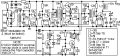
Please,I am was confused at some of the stages as follows 1) The stage coupled directly to the VFO: Please is this an IF amplifier or a buffer? The limited literatures I have been able to contact show that a VFO's output is coupled to a buffer (unity gain but I calculated the gain of that transistor circuit and got 2.36.(2) Is the last circuit before the PA an RF amplifier? (3) I have not been able to find a 10.7MHz IF transformer but it seems to me that the IF transformer acts as a filter as well as a coupler. So can I replace it with a filter circuit and in what way (the circuit diagram)? What effect will it give to the transmitter? (4). I was not able to get a 44.9333MHz crystal but a 47.5MHz crystal. Can I use this and if yes, how can I finally achieve the same 145-146MHz transmission frequency.(5) Please what are the inductance values of the coils (L1-L3 and T3), or, with what wire gauge and core diameter were the turns achieved.
Please the link to the FM heterodyne transmitter I am refering to are as follows: http://forum.allaboutcircuits.com/showthread.php?t=13137&highlight=heterodyne+transmitter
http://web.telia.com/~u85920178/tx/fm-tx1.htm
I sincerely appreciate you all.
Please,I am was confused at some of the stages as follows
1) The stage coupled directly to the VFO: Please is this an IF amplifier or a buffer? The limited literatures I have been able to contact show that a VFO's output is coupled to a buffer (unity gain but I calculated the gain of that transistor circuit and got 2.36.(2) Is the last circuit before the PA an RF amplifier? (3) I have not been able to find a 10.7MHz IF transformer but it seems to me that the IF transformer acts as a filter as well as a coupler. So can I replace it with a filter circuit and in what way (the circuit diagram)? What effect will it give to the transmitter? (4). I was not able to get a 44.9333MHz crystal but a 47.5MHz crystal. Can I use this and if yes, how can I finally achieve the same 145-146MHz transmission frequency.(5) Please what are the inductance values of the coils (L1-L3 and T3), or, with what wire gauge and core diameter were the turns achieved.Please the link to the FM heterodyne transmitter I am refering to are as follows: http://forum.allaboutcircuits.com/showthread.php?t=13137&highlight=heterodyne+transmitter
http://web.telia.com/~u85920178/tx/fm-tx1.htm
I sincerely appreciate you all.