Facebook
 Google
 GitHub
 Linkedin
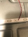
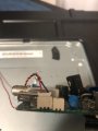
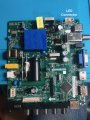
I have an RCA RT4038 tv with a non working backlight issue, 2 LED's were blown. I replaced the strips & tested them, all tested good with 15.5 v required to illuminate all. I also replaced the led driver IC SN51DP but still no backlights. When I checked the voltage output (unloaded) I get 42v. I know that driver is suppose to adjust to the proper voltage when connected to the load but for some reason I am not getting illumination when connected. What am I doing wrong? What might be at fault? I checked most of the related components but everything seemed ok. Maybe I missed something? I did not remove any resistors for testing.
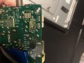
Testing with 3 pin connector attached, I have -35v in standby, not sure there should be any voltage there until powered on? . Powering on, voltage climbs to -90v before settling down to -41v steady, no illumination. Voltage appears to be reversed at connector. Connection from LED's has black as positive and red as negative, connector on the board is the opposite. That doesn't seem right because polarity matters unless there's some type of reverse bias that's suppose to happen. Getting myself confused & tempted to remove the connector on the board and spin it. :thinking:
Update: I spun the board connector around so that the positive side pin went to the positive side of the LED's. When I applied power. I got 3.3v, rose to a max of 14.5v at the connector, and the LED's were full bright & strobing. Not what I was hoping for so I just put back the way it was and here I am, head spinning. It appears that there must be some type of reverse biasing that suppose to place to turn on the LED's that isn't happening for some odd reason. I'm stumped. Maybe the replacement driver IC I got from China is defective?
Attachments
-
 3.1 MB Views: 3
Last edited: