RC High Pass Filter

Thread Starter

chrisjsmith

Joined Nov 12, 2016
41
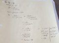
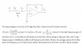
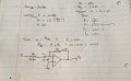
I have completed most of the question for the most part. The last 2 questions have caused a little confusion where I'm asked to find the output voltage given the input frequency to be 1.5 Khz and 150 hz + the roll off db per decade.
I found the voltage gain ratio to be 10 but Vo/Vi = 10
but to get the output voltage when I wasn't given the input voltage not sure if i'm to make an assumption
It would be straight forward question if the input voltage was provided. Is there A way to deduce the Vo/Vi values from the Transfer function.
Please guide me
 

Attachments

The Electrician

Joined Oct 9, 2007
2,971
I found the voltage gain ratio to be 10 but Vo/Vi = 10
but to get the output voltage when I wasn't given the input voltage not sure if i'm to make an assumptionω
I don't understand your confusion here. Vo/Vi is the voltage gain ratio, and it should be 10; what's the problem?

The problem asks "What is the voltage output of the filter...". You pick an arbitrary input voltage (such as 1 volt), and calculate the output voltage for the two given frequencies. Then you can calculate Vo/VI and see if the roll-off rate per decade is as expected.

By the way, when you calculated R1 for a 2500 Hz corner freq, you forgot that ω =2*Pi*f; don't neglect the 2*Pi part.
 

Thread Starter

chrisjsmith

Joined Nov 12, 2016
41
I don't understand your confusion here. Vo/Vi is the voltage gain ratio, and it should be 10; what's the problem?

The problem asks "What is the voltage output of the filter...". You pick an arbitrary input voltage (such as 1 volt), and calculate the output voltage for the two given frequencies. Then you can calculate Vo/VI and see if the roll-off rate per decade is as expected.

By the way, when you calculated R1 for a 2500 Hz corner freq, you forgot that ω =2*Pi*f; don't neglect the 2*Pi part.
Hello, thanks for pointed that out. My problem was I was uncertain if I had to make the assumption for the input voltage
appreciate the feedback
 

Thread Starter

chrisjsmith

Joined Nov 12, 2016
41
I don't understand your confusion here. Vo/Vi is the voltage gain ratio, and it should be 10; what's the problem?

The problem asks "What is the voltage output of the filter...". You pick an arbitrary input voltage (such as 1 volt), and calculate the output voltage for the two given frequencies. Then you can calculate Vo/VI and see if the roll-off rate per decade is as expected.

By the way, when you calculated R1 for a 2500 Hz corner freq, you forgot that ω =2*Pi*f; don't neglect the 2*Pi part.
What do you think?
Can you share with me some literature where I can understand filters that incorporate op amps please?
 

Attachments

The Electrician

Joined Oct 9, 2007
2,971
What do you think?
Can you share with me some literature where I can understand filters that incorporate op amps please?
The opamp is being used in inverting configuration so the high frequency gain (K) is -10, not +10. This will affect the phase angle.

As for literature, search for "active filters". The Wikipedia page https://en.wikipedia.org/wiki/Active_filter has some references at the bottom of the page.
 
Top