Facebook
 Google
 GitHub
 Linkedin
I have a range hood "Ancona" The helogen lights are not operating, I suspect the transformer maybe faulty. I have tried replacing the bulbs.
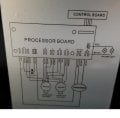
I am now deciding to replace it with LED lights G4 3v. My question is as follows based on the Circuit Diagram (attached)
1. Is the input to the transformer 110v, I now output of is 12v
2. I have a LED driver 110v to 12v. Can I use this driver instead of the transformer. (attached)
3. The transformer has 3 output wire (White, Yellow, Green) I assume white is negative, yellow is positive and green ground, is that right?
4. The LED driver has 4 wires a) 2 white as input, 110v, b) 2 wires, 1 Black & 1 Red which of these are positive and negative?
5. Will the heat of the range affect the LED Driver.
Would appreciate your reply
Thanks
FLDS
Attachments
-
145.3 KB Views: 25