Random 0 or 1 generator

kiroma

Joined Apr 30, 2014
180
Any deviation from a 50% duty-cycle for that multivibrator due to component tolerances, particularly C1 and C2, will reduce the chance to less than 50-50 for a particular LED to light.
He can trim it. Either on the resistors or the capacitors. If the frequency isn't a thing, just one is enough.
But it will obviously drift with time.
I once built a -60 dB 60 Hz stopband filter, trimmed it so well that it went to -80 dB easily. Next day it was -61 dB with no changes made.
 

crutschow

Joined Mar 14, 2008
38,784
Only that the duty cycle is not 50% with this schematic. IIRC, the only way for it to be 50% is using 2 resistors and 2 diodes on the timing part.
No.
When you divide a signal by two, the output has an inherent 50% duty-cycle, independent of the input duty-cycle, if the input frequency is stable.
It's the output duty-cycle of the FF that's important.
Think about it.
 
Last edited:

WBahn

Joined Mar 31, 2012
33,155
Is there a simple circuit that can do this? What I have in mind is a circuit where the operator pushes a button and then after an interval of time the circuit stops running and has an output that is either high (1) or low (0) and this occurs randomly. Searching on the web for this, the results that I get are mostly generators that will randomly produce a range of numbers.

Thanks in advance,
Pete
On question that I haven't seen touched on is how random does it need to be? If comes out 0 49.99% of the time and comes out 1 50.01% of the time, is that unacceptable? If it comes out 0 45% of the time and comes out 1 55% of the time, is that good enough for your purpose (which we have no idea what that purpose is).
 

Thread Starter

PeteHL

Joined Dec 17, 2014
594
Only that the duty cycle is not 50% with this schematic. IIRC, the only way for it to be 50% is using 2 resistors and 2 diodes on the timing part.
The cross coupled flip-flop changes state on the positive edge of the clock. The duty cycle of the wave of the clock has no affect on the duty cycle of the output of the flip-flop.
 

Thread Starter

PeteHL

Joined Dec 17, 2014
594
On question that I haven't seen touched on is how random does it need to be? If comes out 0 49.99% of the time and comes out 1 50.01% of the time, is that unacceptable? If it comes out 0 45% of the time and comes out 1 55% of the time, is that good enough for your purpose (which we have no idea what that purpose is).
45% and 55% would be fine. The application that I have in mind is for double blind testing of an audio processing device. The random 0 or 1 generator determines audio reproduction that is conventional or including the audio processing without my knowledge. Then I compare what I have just listened to with reproduction where the output of the random generator has been inverted. I don't know which i had heard first and what I heard second. I would include a means for determining which came first and which came second after I've finished listening to the two trials.
 

Thread Starter

PeteHL

Joined Dec 17, 2014
594
When you first turn on the power supply voltage to Crutschow's circuit and the pushbutton switch of his circuit is open, what is the state of the Q output of the flip-flop?
 

crutschow

Joined Mar 14, 2008
38,784
When you first turn on the power supply voltage to Crutschow's circuit and the pushbutton switch of his circuit is open, what is the state of the Q output of the flip-flop?
Random/unknown.
Is that a problem?
If so, a power-on reset circuit can be added to set the FF to a known state.
 
Last edited:

Thread Starter

PeteHL

Joined Dec 17, 2014
594
Random/unknown.
Is that a problem?
If so, a power-on reset circuit can be added to set the FF to a known state.
That is what I suspected the answer would be. Not a problem. But it's a little odd, there really is no data. Even Don Lancaster in his book avoids attempting an explanation. Even if he did, I'm sure it would be difficult to follow. Thanks for your engineering Crutschow.
 

MrChips

Joined Oct 2, 2009
35,147
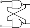
This is a basic flip-flop circuit.

1789436110221.png

The S and R inputs are usually pulled to Vcc with pull-up resistors.
See if you can follow through the logic.

On power on, there is a race problem, meaning that the outcome of the circuit depends on the propagation delay within the circuit. We are looking at nanosecond delays. We cannot predict which gate will win. In practice, there are physical properties in the gates that will consistently give the same outcome.
 

AnalogKid

Joined Aug 1, 2013
12,266
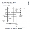
I vote for the 555 astable as the solution. And - use a CMOS 555.

The bipolar 555 needs extra care and feeding to produce a 50/50 output. Even with the single-feedback-resistor circuit, the part has a very asymmetrical output stage that skews the output probabilities. The CMOS 555 has an almost perfectly symmetrical output stage, so you get a near-perfect 50/50 output with very little effort.

CMOS 555, single-resistor circuit, 1 MHz frequency. No need for a separate timer to assure that the oscillator runs for a minimum length of time (or the same length of time) each cycle.

Another option is any Schmitt trigger logic gate, such as a hex inverter or quad NAND gate. If you need multiple randomizers, this gets you 4 or 6 in a single IC.

Here is the single-resistor astable circuit:


1789443684820.png

ak
 

MisterBill2

Joined Jan 23, 2018
28,215
For a CHEAP random 0/1 generator, how about a CD4013 clocked by a burst of ambient noise to the clock input? It will even have the compliment. You will need to gate the input to the "clk" pin, though.
 

crutschow

Joined Mar 14, 2008
38,784
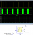
EDIT: Circuit changed, as my previous circuit had a flaw due to leakage currents causing a possible change in the held state over time:

For AK's 555 circuit in post #33 a good question is, how can you readily latch the oscillations at either a high or low output without additional active circuitry.
An interesting way to do that is to put a PB switch in series from the output to the CV input.
When connected, this changes the TRIG threshold to 0V when the output is low, or the THRS threshold to Vdd when the output is high, preventing it triggering to the next state and stopping the oscillation (LTspice sim below):
(Note that the PB needs to be a NC (Normally Closed) type since the circuit only oscillates when the PB is open).

Bottom trace is expanded to show the 50-50 symmetry of the oscillation.

1789602411416.png
 
Last edited:

WBahn

Joined Mar 31, 2012
33,155
You could probably get a suitable circuit for this application by simply putting a push-button switch on a T-type flip flop's clock signal and letting the switch bounce do the rest. Personally, I would probably not do this because, knowing my luck, I'd end up getting the world's first cheap bounce-free switch.
 

kiroma

Joined Apr 30, 2014
180
No.
When you divide a signal by two, the output has an inherent 50% duty-cycle, independent of the input duty-cycle, if the input frequency is stable.
It's the output duty-cycle of the FF that's important.
Think about it.
Got it. You take a whole period to flip the bit, so no matter what is the duty cycle, it's 50/50.
 
Top