Random 0 or 1 generator

Thread Starter

PeteHL

Joined Dec 17, 2014
594
Is there a simple circuit that can do this? What I have in mind is a circuit where the operator pushes a button and then after an interval of time the circuit stops running and has an output that is either high (1) or low (0) and this occurs randomly. Searching on the web for this, the results that I get are mostly generators that will randomly produce a range of numbers.

Thanks in advance,
Pete
 

wayneh

Joined Sep 9, 2010
18,154
I'm thinking of a comparator with a floating input, maybe with an antenna or whatever signal prep is needed to feed ambient EM noise to the comparator. The comparator output can be one of two states, and so that turns the noise into a logical 0 or 1.

Wire the output to feedback to the input once the user pushes a button. As long as the button is held, the state of the comparator is no longer changing.

Problem: To give a random output resembling a coin flip would require the comparator to be outputting equal (average time) 0 and 1s. You could probably get pretty close by tuning the input bias versus the reference but the result may change as the input noise changes. Hmmm...
 

dl324

Joined Mar 30, 2015
18,454
It's fairly straightforward to do this since an operator will be pressing the button. Just have a high frequency oscillator that runs while the button is pressed. Have that trigger a counter that increments a fixed number of times after the button is released. Have the LSB of the counter display the output - which will either be a 1 or 0.
Searching on the web for this, the results that I get are mostly generators that will randomly produce a range of numbers.
You can make the range of numbers 2. But to do that, you need to use a microcontroller.
 

Thread Starter

PeteHL

Joined Dec 17, 2014
594
When the button is released the output of the circuit should be a stable 0 or 1. So the question is in your circuit, what does the pushbutton control?
 

MrChips

Joined Oct 2, 2009
35,127
Answer #5 is the simplest way. And it is as truly random as you can make it without a lot more work.
With the addition of #6. The duty cycle needs to be 50%.

What does the button control?
You can use the button to be one of the two inputs of a NAND or AND gate. The button gates the clock signal that is then fed into the clock input of a toggle flip-flop. We can show you how to create a toggle flip-flop if you need help.

You can also use a D-type flip-flop without needing the extra gate.
 

crutschow

Joined Mar 14, 2008
38,767
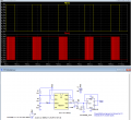
Below is the LTspice sim of an example random output circuit using a 555 oscillator, with a CD4013 flip-flip as a divide-by-two counter.
U1 toggles at 1/2 the 555 frequency (red trace) as long as the PB switched is closed (yellow trace high) and then stops at a random value when the PB is released.

Since the FF signal output duty-cycle when toggling is 50% (differing from that only by any oscillator jitter and difference in high-low/low-high FF propagation delays), and the actual start and stop time from the PB is arbitrarily random, the chance of the static output of the FF being a 1 or 0 is essentially the ideal 50% probability of a random coin flip.

1789367938519.png
 
Last edited:

crutschow

Joined Mar 14, 2008
38,767
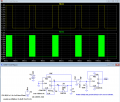
Here's a variation that uses just one CD4013 dual-FF IC:
One half acts as an astable oscillator, and the other half as the divide-by-two counter.
The oscillator has a very unequal duty-cycle but that doesn't affect the circuit operation.
(Note: Do not omit R2, as it generates a minimum Q pulse-width using the stray capacitance at the CLR input).

It also takes much less power, requiring <0.1mA operating current.

1789415759674.png
 
Last edited:

Wendy

Joined Mar 24, 2008
23,811
I always used a simple flip-flop hooked up to an oscillator through the a push-button. The duration of the button push combined with a fast oscillator, yields an unknown result until you let go of the button. There is no way you can control the output to the degree necessary to favor the results one way or the other, so it is essentially random.
Something I've wanted to try is to take a mildly radioactive source, which are everywhere. Connect it to a simple Geiger circuit and set the duration for whatever gives you a one or zero. Given quantum mechanics, this would be a true random number.
 

kiroma

Joined Apr 30, 2014
180
Below is the LTspice sim of an example random output circuit using a 555 oscillator, with a CD4013 flip-flip as a divide-by-two counter.
U1 toggles at 1/2 the 555 frequency (red trace) as long as the PB switched is closed (yellow trace high) and then stops at a random value when the PB is released.

Since the FF signal output duty-cycle when toggling is exactly 50%, and the actual start and stop time from the PB is arbitrarily random, the chance of the static output of the FF being a 1 or 0 is essentially the ideal 50% probability, a random coin flip.

View attachment 371273
Only that the duty cycle is not 50% with this schematic. IIRC, the only way for it to be 50% is using 2 resistors and 2 diodes on the timing part.
 
Top