Radio Shack Power Supply

MSFTF

Joined Aug 11, 2017
33
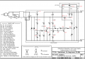
When I worked on overload protection designs, I often had trouble with overloads tending to cause the overload protection to oscillate rather than latch up. I had to go back and do a lot of editing as my interpretation of the circuit changed, thanks largely to your input.
 

AlbertHall

Joined Jun 4, 2014
12,628
It is strange. I did an LTspice but using its standard NPN transistors so the gain of the final transistor will certainly be wrong. What the Q1 circuit does is, when the output voltage is lower than about 7.5V, it only allows Q1 to turn off, and therefore enable the output, in pulses. Above 7.5V, Q1 is turned on all the time and so this part of the circuit does nothing.
 

Attachments

MSFTF

Joined Aug 11, 2017
33
I added some series resistance to the AC power source of that LTspice circuit and then tried different loads on the output.
 

dendad

Joined Feb 20, 2016
4,639
Check Q3 and Q2 as well. If Q4 died, it may have taken Q3 with it.
And what is the volts across ZD1?
It would be a good idea to measure the voltage on each pin of the transistors, and anywhere else you want, and write it on the circuit. We could compare the readings to what is on the original circuit and we may be able to help more.
 

Thread Starter

Fisher77

Joined Sep 19, 2016
32
Indeed, it appears shorted from base to collector, keeping it from turning off. That explains all the connections to it being at the collector voltage. If Q4 is out of the circuit, it is simpler to check Q3. Usually bipolar transistors fail by developing a short circuit from collection to emitter. While it is out, is is a good idea to check it's driver, Q3.
I checked Q3 and it is good. While I was at it I checkd Q1 and Q2. Q2 was blown also. Went ahead and checked
all the resistors and diodes, they were all good to go. I am going to get a new Q4, and Q2 tommorow. I was wondering
if a 2n2222, or 2n3904 would work for Q2 in case the only electronics store in town does not have the 2SC9014,
or it's NTE123AP equivalent?

Check Q3 and Q1 as well. If Q4 died, it may have taken Q3 with it.
And what is the volts across ZD1?
It would be a good idea to measure the voltage on each pin of the transistors, and anywhere else you want, and write it on the circuit. We could compare the readings to what is on the original circuit and we may be able to help more.
I will check the voltages and post them tommorow.
 
Last edited:

MSFTF

Joined Aug 11, 2017
33
Of those two I would pick the 2N2222 because it is heavier duty. I looked at the diagram again to try to see if the bigger pulses from the higher voltage transformer could have blown Q1, but that didn't look likely to me. But just in case I'd go with the 2N2222.
 

Thread Starter

Fisher77

Joined Sep 19, 2016
32
Of those two I would pick the 2N2222 because it is heavier duty. I looked at the diagram again to try to see if the bigger pulses from the higher voltage transformer could have blown Q1, but that didn't look likely to me. But just in case I'd go with the 2N2222.
My mistake with a typo. It was Q2 that was blown. I corrected it in post 25. I replaced it this morning.
Hooked up the new transformer, and while checking voltage that dendad suggested to post, it fried R7 and Q2 again.
 

MSFTF

Joined Aug 11, 2017
33
Was that probe slippage? If so, I feel for you.

Here is an interpretation I have. When Q4 was internally shorted, it reversed biased Q3, basically causing it to act like a zener. That could be a damaging situation for a transistor. Well, anyway, that allowed extra current to flow into Q2, destroying it. If my assessment is right, I recommend checking Q3 and Q4 again. Sometimes damage to a transistor can cause it to get leaky, too, instead of shorting all the way.

When Q2 internally shorted, that destroyed R7 as far as I can determine.
 

Thread Starter

Fisher77

Joined Sep 19, 2016
32
Was that probe slippage? If so, I feel for you.

Here is an interpretation I have. When Q4 was internally shorted, it reversed biased Q3, basically causing it to act like a zener. That could be a damaging situation for a transistor. Well, anyway, that allowed extra current to flow into Q2, destroying it. If my assessment is right, I recommend checking Q3 and Q4 again. Sometimes damage to a transistor can cause it to get leaky, too, instead of shorting all the way.

When Q2 internally shorted, that destroyed R7 as far as I can determine.
Thanks MSFTF.

No it wasn't proble slippage this time, although that has happed more than once, and no doubt will prolly happen again.

I will check Q3 again.

When I was testing the voltages on the board, I had Q4 out of the circuit. Don't know it that cased the problem or not, but I figure is unlikely that it did?
I replaced the resistor, and the new Q2 I got this morning with a 2n2222A, and the 2222 went up in smoke as soon as I switched the PS on. Bear with me I am learning here. So what I gather from what you are telling me about Q3 and looking at the schematic, Q2 runs the base of Q3 telling it to switch on. Q3 then runs the base of Q4 which is what causes Q4 to regulate. Is that correct, or am I completely off there?

Update: Tested Q3 and it is toast. Any general purpose transister I can use here, or is it a trip back to the parts store?
 
Last edited:

MSFTF

Joined Aug 11, 2017
33
You're welcome, Fisher77. The experience for the better is something to go after. Hopefully with minimal downsides.

Powering it up having Q4 out, with no load, shouldn't hurt it. That should have been OK.

Q2 let's Q3 conduct, and Q4 amplifies the current from Q3. I think you are increasing your understanding.

I think Q3 has extra need to be a little heftier than original because power dissipation in linear circuits occurs according to the square of the voltage. In this case, the transformer voltage is higher.

I think I would add some resistance in an early stage of the power input to the circuit to help in trying avoid parts continuing to go bad during troubleshooting. Often an incandescent light bulb is placed in series with the primary of the transformer. In that case, Q4 would be in the circuit so that it can cause the light bulb to dissipate the power that would otherwise blow Q4 and other components. Q4 helps protect weaker components, and the light bulb helps protect Q4.
 

Thread Starter

Fisher77

Joined Sep 19, 2016
32
Thanks for the tip MSFTF. I have been meaning to build a dim bulb tester, just have not gotten around to it yet.
The other problem is finding a incandescent bulb around these parts. They are few and far between now since the
government banned them and made everyone go to halogens, or LED's.

I replaced Q4 with a 2n4383, and Q2 with another 2SC9014. Started taking voltages again and the ole slip of the probe
took care of the second 2SC9014. I knew it was coming. I dropped in a 2n2222 to finish the voltage readings. All voltages
were taken with the Q4 out of circuit and are in red. My concern at this point is the almost 12 volts more that Q4 is going to have to drop. Let me know If I should change anything, or modify the circuit.
 

Attachments

Last edited:

dendad

Joined Feb 20, 2016
4,639
Try a 2 x of 12V tail light lamps in series on the transformer secondary or a 24V one if you can get it. Auto parts stores have them.
For higher powered tests, use headlight lamps.
I've kept a couple of 240V (here in Oz) lamps for fixing power supplies and have set up a power board with the lamp socket wired in series. It is a very handy piece of test gear. And a few 24V lamps too as most of the boards I make run on 24VDC.

How big is the heat sink? Also, a 12V fan out of an old PC power supply would be a good idea, connected across the output and mounted on the heat sink.

You could add one of these before Q4 to drop the voltage to 18V, lowering the dissipation of Q4, but still having analog regulation for better noise figures.
Even 2 in parallel for more current capability.
http://www.ebay.com.au/itm/2X-LM259...128903?hash=item4894aecc87:g:XTkAAOSw5cNYFzQr

There are other small boards on Ebay too.
Just make sure the input voltage rating is sufficient.

For a more low tech solution, these in series with the +out of the bridge rectifier, or from the +ve on C1/C2 to the rest of the circuit will drop about 1.5V per pack.
http://www.ebay.com.au/itm/5PCS-NEW...529327?hash=item2caddd676f:g:HroAAOSw0fhXiZ8~

Don't connect the AC pins to anything, and have the + pin to the Q4 direction and the - to the C1/C2 direction. A few in series will lower the volts quite a bit.
 
Last edited:

Thread Starter

Fisher77

Joined Sep 19, 2016
32
Thanks for the help dendad.

The heat sink is 2.44" x 3.26" or 62mm x 83mm.

Not enough room inside the case for a fan. I could mount one on the outside blowing through the
vent holes. That would be the only option.

I have a couple of buck converters around here somewhere. I cant remember the specs on them,
but I bet I could find out. Might say on them. I will have to find them.
 

MrAl

Joined Jun 17, 2014
13,711
Hello,

If this still applies..

If you have a transformer that puts out a voltage that is too high then as long as the bridge rectifier can handle the extra voltage (check that). then one sneaky way to get a lower voltages is to simply add diodes on the DC side of the rectifier. The diodes will drop the extra voltage and so you'll have close to the original voltage again.

The diodes do drop voltage and since they conduct current that means they will dissipate power, and that is energy lost, but if this is to be used as a test power supply then it does not matter as much because it wont run long at high current anyway. If it is to be used constantly though then you might want to find a better way.

The diodes have to handle more than the max current, so if the max current is 3 amps then go with 5 amp or better diodes. They will drop around 0.7 to 0.9v each so you probably need about 6 diodes in series, but you can try 5 and go from there, adding another diode or two if needed.

This is just another possibly solution. If the unit runs constantly though it will be very inefficient. If it just ahs to run for a little while though it doesnt matter very much.
It is a linear power supply anyway so it's going to be inefficient with higher current and lower output voltage no matter what you do, except of course unless you add a buck front end.
 

ronsoy2

Joined Sep 25, 2013
71
Best bet is to forget that piece of antique junk. You can save up 40 bucks much easier than you can screw around with that old thing. Buy one of these and have a VERY NICE power supply! Ebay 162551869713
 

MSFTF

Joined Aug 11, 2017
33
You're welcome, Fisher77. I could give you a few from my stash of incandescent bulbs if you lived nearby. The Dollar Tree store still has some for sale, and I think hardware stores sell special application ones for candelabra fixtures and other things.

I hate that probe slippage thing. I and my partner techs used to make probes out of things that were more slender and pointier than usual DMM probes. Then we put insulation like heat shrink tubing or something similar on them so that just the very tip end was exposed.

Based on those new voltage readings, it looks like it should operate OK.

I like the idea of giving output Q4 a lower voltage supply. That type of thing was a common practice for vintage audio amplifier designs.

I think I would try disconnecting the negative of the bridge rectifier from the circuit. You could do that by removing it from the circuit, bending that pin out of the way, and then resoldering it back onto the board. Then the transformer center tap is connected there instead. The AC input pins of the rectifier then get supplied by the two 12v winding ends of the transformer like usual. That gives you about 16v full wave rectified DC that would power Q4 and the bulk capacitors.

Then take the 12v windings and also have them power capacitive voltage doubling circuitry. That would supply the rest of the circuit other than Q4 and it's big filter capacitors on its collector with over 30vdc.

Alternately, simpler but less efficient, a voltage dropping resistor can be placed in series with the collector of Q4. I figure that under a load, the DC voltage will sag to just under 30, so at full current of 3 amps, a power resistor could drop about 15v, which is 45 watts that Q4 would be spared from having to dissipate. Resistors like the sandstone type wire wound ones can take heat stress a lot better than semiconductors like bipolar transistors. Well, v=ir, so solving for r gives 5 ohms because v=15 and i=3. For a little more voltage headroom so Q4 doesn't clip so readily, 4 ohms would be a good standard value, a little lower than the 5 ohms, which, anyway, is a rarer resistance value to find.
 
Top