Radio Controlled Activation Unit

Thread Starter

frogy

Joined Dec 24, 2007
11
3. Nothing is obvious in a circuit I haven't seen. :confused: Can you draw the circuit that shows exactly how you intend to connect the SCR to the driver transistor to the R/C receiver.

The devil's in the details. ;)

Ken
I have drawn the circuit that I'm using and posted it previously in between your posts...


I'm going to have to connect the Collector of the PNP to the Gate...

Would I connect the Cathode of the SCR to the -330v [cap-] and 0v [receiver-] ground?

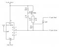
Combining the two schematics I got this...


The Cap-/Blue part of Load/Flash is connected to the -1.5v\0v (negative of AA/C/D), so really the cathode if the SCR is already connected to the -1.5v, so it should switch fine from the PNP
 

KMoffett

Joined Dec 19, 2007
2,918
The whole circuit helps a lot. Only other thing I would do, is move Load resistor to between the PNP's collector and the SCR's gate. Right now, when the transistor turns on, the the receiver's battery is shorted by the PNP's Vsat (0.2V) and the SCR's gate-to-cathode forward voltage (0.7v), with no current limiting. A 10 ohm resistor [ (1.5v-0.2v-0.7v)/50mA ] should be OK for the Load.

Oops!...now, another problem occured to me. My PNP drive circuit was only intended to drive logic level signals...specifically cmos gates at 5V...very little current. I'm not sure the 2N3906 in my circuit has enough gain to drive 50mA for the SCR from a 1.5V source.

I'll have to think about that... :rolleyes:??? ...but got to go to work now!

Ken
 

KMoffett

Joined Dec 19, 2007
2,918
frogy,

OK..."take" two or three or whatever... ;)

Attached is a circuit I tried, and is capable of driving an SCR's gate with a maximum of 56mA from a 1.5v bench supply. The two 10 ohm resistors in parallel (or one 4.7 ohm) limits the current. If you don't need that much current (your drawing shows 9-30mA) this resistor(s) could have a higher resistance to reduce the battery drain. One 10 ohm resistor limits gate current to about 28mA...a 22 ohm, to about 10mA. Use the highest resistance that still reliably triggers the SCR. The resistor from gate to cathode makes sure the SCR stays off when not triggered.

Hope this makes sense.

Ken
 

Attachments

Thread Starter

frogy

Joined Dec 24, 2007
11
The Circuit looks good to me... Thanks a lot!

I may drive a monostable 555 instead to prevent accidental after-firing until the capacitors of the flash circuit are thoroughly re-charged, but I know how to do that part...
 
Top