Beginners try at a 12V Radio-Controlled Door

Thread Starter

ovlis

Joined Apr 15, 2025
3
Hi,

I'm trying to build a 12V radio-controlled door.

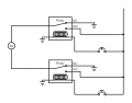
I'm using this receiver module (https://de.aliexpress.com/item/4001...t_main.15.154b5c5fXvHEls&gatewayAdapt=glo2deu), which outputs via two relays. When I press a button on the remote, one relay powers on and stays on until I press the button again, same with the other button but different relay, allowing me to reverse the motor polarity.

So far, so good, but I don't want to press the button again to stop the motor. Ideally, the motor should stop automatically when the door hits, for example a limit switch.

If I cut power to the receiver for at least one second, the relays reset, which is currently my best idea. But I wouldn't know how to do this.

Is that a good idea and if yes, how would I do that?
 

Tonyr1084

Joined Sep 24, 2015
9,744
Welcome to AAC.

The receiver will need to be modified if you want a limit switch arrangement.

What kind of door are you remotely opening and closing?
If opened and closed by a motor, can it be operated manually if there's a power failure?
 

Thread Starter

ovlis

Joined Apr 15, 2025
3
Thank you for welcoming me!

The motor just lowers an electric horse fence so you can drive over it. You can still open it manual from the other side.
I have tried to understand the receiver to modify it with little success...
 

Tonyr1084

Joined Sep 24, 2015
9,744
For starters we're going to need a schematic of the relay module. That way we can begin to understand how it operates. For instance, if you interrupt the coil current will that cancel the closure of the contacts? If not - then an understanding of how it latches and how it is held latched.

Switching the 12V on and off using limit switches won't work. At first I was thinking you could interrupt it that way. But then when the door (or fence) is fully opened or fully closed the relay module would have no power with no way to bypass the limit switches. The answer is going to lie in limit switches that control the relay directly.
 

Tonyr1084

Joined Sep 24, 2015
9,744
This is one way of limiting the door / gate / fence:
Screenshot 2025-04-15 at 10.52.25 AM.png
The UP Limit and DOWN Limit switch relays off, each controlled independently of the other. The Momentary UP and DOWN buttons energize the relay for as long as you hold the momentary button. When the limit is reached power is cut off to the relay and it drops back out.

Instead of the Momentary switches you can incorporate your remote control board. You can press the DOWN button and if the relay latches on your module then it will run till it hits full limit. But if you hit DOWN and the gate lowers half way then you hit DOWN again to stop the downward progress, that will work too.

Notice that the limit switches are NC (Normally Closed) with NC connected to one leg of the relay and the other is to a common ground. Doesn't have to be earth grounded, just this is a typical way of drawing the return path to the power supply without having to add all those extra lines.

Give this a look over and see if you can come to some sort of decision on how you want to approach this. Adding your own schematic to this thread will be helpful. Pictures of the job at hand would also be useful.

I'll be in and out much of the day. But I'll check from time to time.
 

Thread Starter

ovlis

Joined Apr 15, 2025
3
I had just made a schematic of what I know, it looks very similar to yours. Adding the limit switches where you did is a very good idea I hadn't though of. I'll try just that and see if it works.

The relays are GuoKE GK3FF-12VDC-S-C. they don't have a latch, as they only stay switched when there is current in the coil. So that is good.
I will have to remove the relays from the board and wire them back in, but I'll manage that.

The other idea had been to cut the power only fore 1sec as that resets the switches on the remote control board. But that seems much harder.

Thank you so much for your help.
 

Attachments

Tonyr1084

Joined Sep 24, 2015
9,744
Hey Pete! Haven't seen you in a while.

Yes, aside from having limit switches to prevent over extension, yes, they ARE the same.

The limit switches could also be on the common side (grounded side - not earth ground).
 

ThePanMan

Joined Mar 13, 2020
862
Hey Tony. The kids have been doing some big projects at school. I'll have to text you some pic's.

I didn't think of limit switches on the other side of the relays. But I'm not understanding the four screw connections. Two of them are power and ground. No idea if the relays themselves are SPDT or SPST. Perhaps 12V positive is also the common to the two outputs but then they must be SPST relays. Unless for some unknown reason 12V negative is a part of one relay and the other is positive. There's just not enough data on the device.
I have tried to understand the receiver to modify it with little success...
Yeah, I'd bet. Best to hold off until you know more.
 
Top