R800C and Blue pill schematic

panic mode

Joined Oct 10, 2011
5,178
no headers? how is this supposed to interface to outside world?
no buttons or jumpers or dipswitches? how do you plan to controlling startup mode?
LEDs with 47 Ohm series resistors? that is asking for massive current from GPIO (25mA-ish).
several hundred of uF across battery?
5V zener across battery? how are you planning on charging the battery?
 

Thread Starter

tomyF

Joined Jan 28, 2026
8
> no headers? how is this supposed to interface to outside world?
Connectors have headers to connect to

> no buttons or jumpers or dipswitches? how do you plan to controlling startup mode?
The device/board is not to be programmed often; mostly it's merely once
I changed my mind a little and connected both NRST and BOOT0 via a cap and resistor (respectively) to GND.

> LEDs with 47 Ohm series resistors? that is asking for massive current from GPIO (25mA-ish).
I'm going to use a LED Red 620-630nm 0805 25mA 60mW (XL-2012SURC) with a 68 Ω resistor for both LEDs in my design.

> 5V zener across battery?
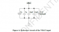
yes, below is from the SIM's hardware design
Capture.PNG

> how are you planning on charging the battery?
The battery will be charged using a li-ion 18650 (with protection) module connected to it
 
J3 already gives you 3.3V, SWDIO and SWCLK, so you do have an SWD programming connection.

It looks like pin 4 of J3 is currently unused. I would connect that pin to GND, because the ST-Link and the target board need a common ground reference. I would also consider adding NRST as a separate test pad. It is not always required, but it can be useful if the firmware makes a normal debug connection difficult.

Since NRST is already routed to the reset button, adding a test pad should be easy. With those connections, I don't think a USB connector is necessary just for programming the STM32.
 

Thread Starter

tomyF

Joined Jan 28, 2026
8
J3 already gives you 3.3V, SWDIO and SWCLK, so you do have an SWD programming connection.

It looks like pin 4 of J3 is currently unused. I would connect that pin to GND, because the ST-Link and the target board need a common ground reference. I would also consider adding NRST as a separate test pad. It is not always required, but it can be useful if the firmware makes a normal debug connection difficult.

Since NRST is already routed to the reset button, adding a test pad should be easy. With those connections, I don't think a USB connector is necessary just for programming the STM32.
Thanks for your points.

Below is my new design. Pin4 of J3 is (already) connected to GND and I connected both NRST and BOOT0 to GNd since the device is (mostly) programmed only once.
 

Attachments

panic mode

Joined Oct 10, 2011
5,178
Connectors have headers to connect to
so where are they on schematics? how are you exposing IO pins? i am expecting to see some 2x 20pin

I'm going to use a LED Red 620-630nm 0805 25mA 60mW (XL-2012SURC) with a 68 Ω resistor for both LEDs in my design.
did you read the datasheet for STM32F1? are you sure PC13 can source 25mA? even if it can it is a bad idea. you do not want to stress or load the most complex part on your board, that is job for transistors. same with LED datasheet. what made you pick 25mA? this is just an indicator, not a flashlight. besides,, datasheet clearly says that breaking point (absolute maximum) for this LED is 20mA, so how in the world did you decide to choose 25mA?

and red LED will have Vf about 1.6-1.7V so

(Vgpio-Vf)/If = (3.3V-1.7V)/5mA= 320 Ohm. the nearest common value is 330 Ohm.

below is from the SIM's hardware design
View attachment 370536
ok, zener stays, what about those caps? bypass caps are parallelled to reduce impedance over wide frequency spectrum. so those capacitors need to be different (small, medium, large,...).
the datasheet shows that small value caps are in pF range.the smallest cap you use us 0.1uF.

The battery will be charged using a li-ion 18650 (with protection) module connected to it
that is also not shown in schematics. if this is a BluePillas you call it, i expect to see 2x 20pin. but your schematics shows only couple of pins on J1, J2 and J8.
 
you should have started by posting your own links to datasheets so people willing to help do not have to navigate minefields of clickbait and malicious downloads.
for example R800c datasheet:
https://www.eevblog.com/forum/begin...ue-pill-board/?action=dlattach;attach=2713183

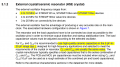
but this is incomplete. for detailed electrical specs you need to keep searching. then you will find that absolute max Sink/Source current is only 2mA per pin. so you should never drive LED directly by some IO pin. that LED on pin 41 is a short circuit as far as R800C is concerned.
 

Thread Starter

tomyF

Joined Jan 28, 2026
8
J3 already gives you 3.3V, SWDIO and SWCLK, so you do have an SWD programming connection.

It looks like pin 4 of J3 is currently unused. I would connect that pin to GND, because the ST-Link and the target board need a common ground reference. I would also consider adding NRST as a separate test pad. It is not always required, but it can be useful if the firmware makes a normal debug connection difficult.

Since NRST is already routed to the reset button, adding a test pad should be easy. With those connections, I don't think a USB connector is necessary just for programming the STM32.
Thanks for your points.
> It looks like pin 4 of J3 is currently unused.
Pin 4 of J3 is connected to GND (if you zoom in enough).

> It is not always required, but it can be useful if the firmware makes a normal debug connection difficult.
As said, the device/MCU is (often) always programmed only once. Could you explain a little more why using NRST still can be useful?

See updated schematic below.
 

Attachments

Thread Starter

tomyF

Joined Jan 28, 2026
8
btw, i did not have time to dive deep. comments are only for few things that stand out and i was not focussing on details.... your schematics has no mention of of frequency or Y2 part number (what happened to Y1?). the 33pF may be too large. for details on making STM32 based product you can use reference documents like:
https://www.st.com/resource/en/appl...x-hardware-development-stmicroelectronics.pdf
Thanks for your points.

> frequency or Y2 part number (what happened to Y1?). the 33pF may be too large.
Y2 is XTAL 8MHZ(HC-49SMD), 8 MHz crystal size 11.4 x 4.8 mm HC-49SMD and I tried to use the caps properly based on its datasheet.

> details on making STM32 based product you can use reference documents
I used the great tut
for the STM32F103C8T6. Do you think still that pdf reference you sent needs to be read?

>you should have started by posting your own links to datasheets so people willing to help do not have to navigate minefields of clickbait and malicious downloads.
for example R800c datasheet
:
You're right, sorry.
I've already also used that pdf file and SIM800C_Hardware_Design_V1.05 (which is quite close to R800C and almost all details) for my schematic.

> absolute max Sink/Source current is only 2mA per pin. so you should never drive LED directly by some IO pin. that LED on pin 41 is a short circuit as far as R800C is concerned.
I checked the R800C/SIM800C documentation and changed it to:
R800C pin 41 (NETLIGHT) → 470 Ω → XL-2012UBC blue 0805 LED → GND
The R800C GPIO voltage is about 2.98 V, and this LED has a Vf of 2.6–3.1 V, so the actual LED current should be quite low (well below the 25 mA LED rating and much lower than with 47 Ω).
So I agree with your main criticism about the 47 Ω resistor / excessive current, although I don't think the correct conclusion is that an LED can never be connected directly to NETLIGHT—the SIM800C documentation itself provides for NETLIGHT driving an LED.
 
about crystal...

products like STM32 support different oscillator options, internal external, low frequency crystal, high frequency crystal...
your schematic shows no crystal part number, just like all your posts so far. for whatever reason you want feedback but choose not to communicate.
and HC-49SMD is not a part number, it is the form factor (package style). many crystals with very different specks are available in that form factor.
your schematic shows net names starting with HSE... which suggests high speed (high frequency crystal).
1787440814571.png

Do you think still that pdf reference you sent needs to be read?
i think you should have started with sentence like that. then you would get zero constructive replies. if you do not want to read, why should i do it for you? when you fail and see that boards you designed, paid for, waited for etc do not work. your stance on reading may change.


i still don't see how did you come up with current limiting resistor for R800C LED.
as already stated 2mA or higher is excessive and will damage it.
you do not seem to understand what the datasheet tells...

2mA is not the rated value.... it is the absolute maximum value - and that means breaking point.
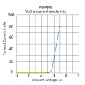
normally one would want to stay at least 25% away from it (if you know to load well enough). but load is nonlinear and you are reading value of the crude graph that someone obviously drew by hand, two straight lines and one curved segment - clearly an approximation, real data never looks like that.

in other words, forget about 25% margin....

so if using GPIO to directly drive some LED, i would choose much more conservative value, such as 1mA.
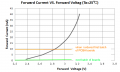
according to datasheet, at 1-2mA, Vf is some 2.5V

1787438911205.png

then assuming the highest possible GPIO voltage (3.3V) resistor value becomes
(3.3V-2.5V)/1mA = 800mV/1mA=800 Ohm and nearest common value is 820 Ohm.

or... if you have the LED, connect it with resistor and measure current draw at 3.3V
 
So now with 2mA as the maximum value for LED current, and 1mA being the preferred choice, I am terribly confused. That is vastly less current than I have powered LEDs with previously.
How is this possible????
 
no... LED can use more current... problem is that IC outputs have absolute limit of 2mA.

btw. today, LEDs exist that will light up rather nicely with 1mA or less ...that is IF one is using the right LED.
i used tons of KT-0805G on IO boards to who state of each IO:
https://www.lcsc.com/product-detail/Light-Emitting-Diodes-LED_Hubei-KENTO-Elec-KT-0805G_C2297.html
look at the VI curve, originally i aimed for 10mA but when boards arrived it was like staring at bunch of laser pointers aimed at your eyes. so quickly, through experiment it was determined that much lower current would be appropriate.
1787453067383.png
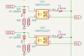
btw, SSR that is powered by same 3V3 GPIO still gets low value resistor, i chose 390 Ohm in this case.

1787452118478.png
 

Thread Starter

tomyF

Joined Jan 28, 2026
8
It was a good point for me (as a beginner of electronics) to properly consider the current a component like and LED can draw and where it comes from. The low current LEDs aren't available in my local so I'm going to use the XL-2012UBC Blue LED with a BC847B transistor just like what the datasheet recommends. BC847B + 4.7 kΩ + 47 kΩ + 100/200 Ω

Capture.PNG
What other components do you need to have their part number and I will post them in the next post.
 
Top