R C Ocillator distortion

Thread Starter

Fluxor1964

Joined Jun 11, 2015
182
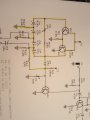
I am building an RC oscillator as part of a project, I have assembled the area of the circuit highlighted in yellow and when I went to test
I found my sine wave output was distorted, I checked my circuit and found one of the transistors I had used was different to the other one, they are now both 2N3904's which improved things somewhat, now I just have a slight deformation on the rising part of the trace, where should I check next please?
is it possible I have a faulty capacitor since all the ones I have used are from my scrap box and are years old, I have heard electrolytics can dry
out after a while and cause problems.

I have checked my wiring and all is good there.

20170118_164133.jpg
upload_2017-1-19_8-47-52.png
 

Attachments

Last edited by a moderator:

DickCappels

Joined Aug 21, 2008
10,180
It looks like you need more voltage (maybe a few tens of millivolts) on the base of Q1 and/or some resistance (560-3k) in series with the emitter of Q1.

I have a problem with the circuit -where does Q1 get its collector current? What plugs into "INPUT"?
 

Thread Starter

Fluxor1964

Joined Jun 11, 2015
182
It looks like you need more voltage (maybe a few tens of millivolts) on the base of Q1 and/or some resistance (560-3k) in series with the emitter of Q1.

I have a problem with the circuit -where does Q1 get its collector current? What plugs into "INPUT"?
The only parts constructed so far are the ones in yellow highlight.....I am monitoring the output from C8 where Q1 base would be if it was
fitted so Q1 is irrelevant at this time.

Neil.
 

DickCappels

Joined Aug 21, 2008
10,180
Its pretty simple then. There is in essence only one transistor, the Q3/Q4 Darlington to worry about and that is the likely place the distortion is creeping in.

Can you post the waveform direct coupled at the base and emitter of Q3?

Maybe switching to a higher gain transistor for Q3 would help. On that note, check to make sure you have the transistors connect correctly -you can swap the emitter and collector in low voltage circuits and they seem to work fine, except the gain is lower, and maybe that is what happened to your circuit.

You can try increasing R9.

(edit) And maybe you need to get the output to a higher voltage, which you can probably do by putting 100k or maybe more from the base of Q3 to ground. Don't try all of these at once.
 
Last edited:

Thread Starter

Fluxor1964

Joined Jun 11, 2015
182
I am trying to exhaust any possibilities with this circuit first but yes, I may switch to an op amp version if all else fails....this is the
third circuit I have tried to get a sine wave oscillator and I just hate to admit defeat lol

Thanks for your advice, I will try your thoughts and see what happens, I may as I have said make a fourth attempt using an op amp circuit if this fails, very annoying since I am sooo close lol.

Neil.
 

AnalogKid

Joined Aug 1, 2013
11,044
1. Note that while the scope shot looks like a DC bias or operating point problem, be aware that a phase shift oscillator is not a low distortion topology.

2. Is this a tremolo circuit?

ak
 

Thread Starter

Fluxor1964

Joined Jun 11, 2015
182
1. Note that while the scope shot looks like a DC bias or operating point problem, be aware that a phase shift oscillator is not a low distortion topology.

2. Is this a tremolo circuit?

ak
yes it is a tremolo for my guitar.......how did you know?

Neil.
 

AnalogKid

Joined Aug 1, 2013
11,044
PAIA schematics in Popular electronics in the 60's. You are driving Q1 as a voltage (or current) -variable resistor. While this will work, the equivalent resistance variation with the sine wave input will be very much *not* sinusoidal. With the DC bias through Q1, it is acting as a diode switch with gain. But diode switch circuits are non-linear, which is why they are usually used as on-off switches rather than variable resistors. Consider a 2N7000 MOSFET as an alternative.

And even if it were perfect, you cannot perceive the difference between a perfect sine wave driving voltage and the small amount of distortion you have.

ak
 

Thread Starter

Fluxor1964

Joined Jun 11, 2015
182
So I recently spent some time breadboarding different phase shift oscillator circuits to try to get a pure sinewave, (four different circuits with op amps) I couldn't get ANY of them to give me an output sooo I rebuilt my original circuit with smaller capacitors and I was delighted to get the output I was looking for.

unfortunately the control pot changes the amplitude and not the frequency that I wanted and reading up on these circuits I now understand to change the frequency I need to alter all three resistor values in unison which is very impractical, is there an easy way to vary the frequency?.....maybe a frequency divider circuit that I can feed the sine wave into?

I am super stoked with my clean output and if I can vary the frequency even slightly I will have what I need.

Neil.20170130_152302.jpg
 

AnalogKid

Joined Aug 1, 2013
11,044
The tops are starting to compress, but overall not bad at all. Definitely better than in your first post. What did you do to fix it? Schematic?

Good clean variable frequency true sine generators are tough. Hewlett and Packard solved it with a very large dual-gang variable capacitor. A phase-shift circuit is reliable and stable, and you can get some freq variation by varying only one resistor, but the range will be narrow. Since you don't need a very wide freq range, consider a dual-gang pot to vary two of the three resistors. They still are fairly common, and you might get lucky on the surplus market.

Also, read up on the 8038. This IC is a full-blown function generator, and derives the sine wave output from the triangle wave with a series of diode breakpoints. It can deliver 1% or less distortion with tweaking, has a wide adjustment range with a single pot, and the sine amplitude is constant.

ak
 
Top