 Facebook
 Google
 GitHub
 Linkedin
Hi!
I'm planning on making my own guitar pedal (boost) and have some questions.
Is through-hole technology or SMD recommended? I see that most pedals are made with THT and not SMD, does anyone know why? One thought I had was that space isn't an issue in guitar pedals, generally speaking, since they all have such large cases relative to the electronics that go inside. But that can't be it, can it? I am personally fine with both, but maybe the community of making DIY pedals is also a bit "used" to mainly going THT?
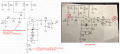
Is the type of component important, or is only the values important when chosing? For an example: this circuit below has several capacitors, some being polarized while some are not (C29 not being and C27 being polarized for an example).

It's from this YouTube video by Wampler Pedals and in the short views you get of the breadboard I can see that he's mostly using film capacitors, with a couple of electrolytic. Now, does it matter what kind of capacitor you use for the circuits performance (this case being for a guitar pedal), or do you only have to make sure the capacitance and max voltage are correct? Does it matter if the capacitor will be used as, for an example, a coupling or decoupling capacitor?
Polarized vs non-polarized: is this just something that the "correct" capacitor happened to be, or is it very important in some situations that a capacitor is polarized? Take C27 and C30: they both have a pretty "large" capacitance, and will therefore probably be electrolytic and therefore probably be polarized. Is this why?
Thankful for all answers!
I'm planning on making my own guitar pedal (boost) and have some questions.
Is through-hole technology or SMD recommended? I see that most pedals are made with THT and not SMD, does anyone know why? One thought I had was that space isn't an issue in guitar pedals, generally speaking, since they all have such large cases relative to the electronics that go inside. But that can't be it, can it? I am personally fine with both, but maybe the community of making DIY pedals is also a bit "used" to mainly going THT?
Is the type of component important, or is only the values important when chosing? For an example: this circuit below has several capacitors, some being polarized while some are not (C29 not being and C27 being polarized for an example).
It's from this YouTube video by Wampler Pedals and in the short views you get of the breadboard I can see that he's mostly using film capacitors, with a couple of electrolytic. Now, does it matter what kind of capacitor you use for the circuits performance (this case being for a guitar pedal), or do you only have to make sure the capacitance and max voltage are correct? Does it matter if the capacitor will be used as, for an example, a coupling or decoupling capacitor?
Polarized vs non-polarized: is this just something that the "correct" capacitor happened to be, or is it very important in some situations that a capacitor is polarized? Take C27 and C30: they both have a pretty "large" capacitance, and will therefore probably be electrolytic and therefore probably be polarized. Is this why?
Thankful for all answers!

")


