Facebook
 Google
 GitHub
 Linkedin
Hey Guys,
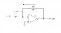
Quick question. The book I'm reading states that with an inverting amplifier setup, the greater the negative feedback, the higher the closed-loop cutoff frequency. In other words, the smaller Av(cl) is, the higher f2(cl) is.
Could someone please explain to me why this is? I'm really trying to understand how the ration of Rf/R1 impacts how much voltage is fed back to the input.
Thanks,
Austin
")