Question regarding creating a boost circuit, 24 to 200V for a solenoid

ronsimpson

Joined Oct 7, 2019
4,771
thank you for all the help!!,
The LT3485 has several versions depending on how much current you want to pull. I chose the -3 which is the highest power version. You might want to back down to a low current version.
The design in the data sheet used a 1:10 transformer and starts with one end on ground. I did not have any of those here. But I have some Coilcraft transformers that have 1:6 turns. (actually 6 coils) The 10:1 is for 300V. You need about 6:1 for 200V.
10:1 is 1 winding with 10 and one winding with 1. We need more like 6 turns and 1 turn but I only have a transformer with a total on 6 windings. There for I made a boost, not a true transformer supply.

Look at the LTspice file. I have some HP2-0083LD transformers. They are very useful when you cannot afford a custom transformer made. The transformers look like this. By parallel and series, the different windings you can make up something useful.
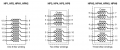
1763328045409.png
When choosing a transformer There are some things to look for. I chose the HP2 or HPH2 because the HP1 seemed small to me. The IC seems to like 4 to 10uH of inductance on the primary. I don't remember but I think there was about 20Vus on the primary so a 30.8VuS is good. The current using the big -3 part was about 1.4 or 1.5A. Because of you long time between charges you might think about using a low current version on the IC and rethinking about the HP1 transformer.

1763328309367.png
If you want to build 10,000 then a special transformer is best. But Coilcraft has these every day.
----------------------------------------------------
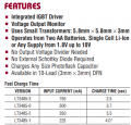
One option is to use a "7808" switching regulator. (less power loss) Then use the regulator on the computer to drop the 8 to 5V.
Run the photo flash IC on 8V or 10V which is it max.
Or use the switching 7805 to run everything. In all cases I think the LT3485-1 uses 1/3 the power and takes 3x longer to charge but might be better in your case.
1763328997798.png

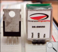
On the 7805 regulators. It will get hot dropping the voltage down form 24V. For some reason I can't find the part numbers today. But several companies make a switching power supply that is a PWM and plugs in just like a 7805 but it does not burn power. One of the companies is in the picture but that is not the one I usually use.
1763329593008.png
 

Attachments

MisterBill2

Joined Jan 23, 2018
27,977
I came across a 24 volt to 300volt inverter in the "SCHEMATICS FOR FREE" website in the POWER section. it used two power mosfets and an AC step-down transformer working in reverse to deliver 3 oo volts at about 2 amps. It should be possible to scale the concept to what the TS requires.
 

Thread Starter

johnvig

Joined Nov 10, 2025
10
The LT3485 has several versions depending on how much current you want to pull. I chose the -3 which is the highest power version. You might want to back down to a low current version.
The design in the data sheet used a 1:10 transformer and starts with one end on ground. I did not have any of those here. But I have some Coilcraft transformers that have 1:6 turns. (actually 6 coils) The 10:1 is for 300V. You need about 6:1 for 200V.
10:1 is 1 winding with 10 and one winding with 1. We need more like 6 turns and 1 turn but I only have a transformer with a total on 6 windings. There for I made a boost, not a true transformer supply.

Look at the LTspice file. I have some HP2-0083LD transformers. They are very useful when you cannot afford a custom transformer made. The transformers look like this. By parallel and series, the different windings you can make up something useful.
View attachment 358979
When choosing a transformer There are some things to look for. I chose the HP2 or HPH2 because the HP1 seemed small to me. The IC seems to like 4 to 10uH of inductance on the primary. I don't remember but I think there was about 20Vus on the primary so a 30.8VuS is good. The current using the big -3 part was about 1.4 or 1.5A. Because of you long time between charges you might think about using a low current version on the IC and rethinking about the HP1 transformer.
View attachment 358980
If you want to build 10,000 then a special transformer is best. But Coilcraft has these every day.
----------------------------------------------------
One option is to use a "7808" switching regulator. (less power loss) Then use the regulator on the computer to drop the 8 to 5V.
Run the photo flash IC on 8V or 10V which is it max.
Or use the switching 7805 to run everything. In all cases I think the LT3485-1 uses 1/3 the power and takes 3x longer to charge but might be better in your case.
View attachment 358981

On the 7805 regulators. It will get hot dropping the voltage down form 24V. For some reason I can't find the part numbers today. But several companies make a switching power supply that is a PWM and plugs in just like a 7805 but it does not burn power. One of the companies is in the picture but that is not the one I usually use.
View attachment 358982

This was really helpful. I took a look at your simulation, and I was able to get 200 v with a 18uF capacitor within 0.12 s. And with this I can also easily turn off the charging and easily monitor the voltage. I went deeper looking at other chips and also found these LT3750 and LT3751 these says they are for charging high voltage capacitors and seem to be much quicker, though that is not so important. I wanted to ask if they might work better in regards to safety or simplicity?, but as you recommended the LT3485-3 should serve my purpose.

Regarding the transformers, the coilcraft transformer seems very interesting, so to confirm my understanding, there are 6 coils and I can connect, 1 of the coil as primary and connect the rest in series to get 1:5 ratio? the equation in the datasheet gets me a transformer ratio of 6.4, but I think the 200 is not critical. So this should be fine.

Regarding the power regulator, yes a switching one would be much more efficient, I found this https://www.mouser.de/ProductDetail/MEAN-WELL/N7809-1C?qs=7D1LtPJG0i1eV0yh2VoHCA== outputting 9v so this could power the microcontroller and the ic and maybe it is enough to power the igbt or mosfet with gate driver which I might have to use for firing the solenoid.

I will do a simulation with all the parts to be sure. thank you for your help again.
 

ronsimpson

Joined Oct 7, 2019
4,771
maybe it is enough to power the igbt or mosfet with gate driver which I might have to use for firing the solenoid.
I have not looked at the IGBT/MOSFET driver 'thing'. When I saw what you proposed I went directly to this circuit. "I have seen this before."
I looked for a 24V capacitor charger, but the parts count was high.
 

Thread Starter

johnvig

Joined Nov 10, 2025
10
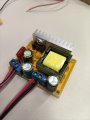
Hey, after a lot of thinking and testing I decided to buy those ali express module(https://www.mouser.de/ProductDetail/MEAN-WELL/N7809-1C?qs=7D1LtPJG0i1eV0yh2VoHCA==). I thank you all for your help, it really helped learn more and get a better understanding but since the price was going quite high to build myself, I bought this for 2.5 euros.... I think this works better for now.

WhatsApp Image 2025-11-27 at 16.50.30_da440136.jpg

I tested the module and I am able to get stable 100 v. But the issues I am now facing is that there is no way to turn off the boost converter. I had some parts so I tested it and I tried to trigger the solenoid using a mosfet while the boost converter was connected at 40v and I can see the bench supply maxing out on the current since converter is trying to bring it up to 40v. I tried turning on the mosfet and turning it off almost immediately but the spike was there for atlease 2 seconds, not sure how much current it will take if the battery was connected. So I have added this in rush current limiter, but not sure how it will work in real life.

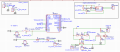
If you have any other suggestions please recommend. the mosfet low side switching(to turn off the boost converter) did not seem to work, and high side switching seems complicated. is there a simple solution? Other than that, please also tell me if there are some changes that you would make. I have added caps to the power lines as recomended and a 100k gate to ground. Also I wanted to be able to control the voltage through software so I have attached this digital pot to be able to replace the potentiometer on the boost converter.

1764446834215.png
 

Attachments

Last edited:
Top