 Facebook
 Google
 GitHub
 Linkedin
Hi all,
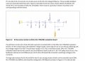
The picture attached is from this User Manual. You can see four resistors of 500k and R7 which is not physically on the board. However, they claim that if you put R7 = 13.3k on either board, you will be sensing 0-3.3V from an input voltage range of 0-420V.
If I say Vsense = (420*13.3k)/(500k*4 + 13.3k) = 2.77V, which is not the range they stated. For 420V I should read 3.3V. Maybe I'm confused or there's some implicit data?
Attachments
-
 166.5 KB Views: 8
")


