question about transistor design

Ron H

Joined Apr 14, 2005
7,063
The first circuit looks to be a small speaker or headphone driver (something with a coil) so I hope it's not a limiter at the mic's normal input levels. :)
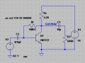
I don't know what it's driving, but the last 3 stages look like limiters to me. With 4 stages, and a gain of 50-100 per stage, the overall gain will be well over 120 dB. I think that most microphones have outputs well above a few microvolts.
 

Audioguru

Joined Dec 20, 2007
11,248
Series negative feedback is used in a bootstrap circuit and parallel negative feedback is used in the OP circuit. So it can be used either way to increase or decrease impedance. My bad for getting them reversed. I stand corrected.
Actually, the bootstrapping makes the input impedance increase because it is positive feedback, not negative feedback.
 

Jony130

Joined Feb 17, 2009
5,598
Granted you might assume that but my old professor would want a proof.
If you do small signal analysis you will get the same result.

Full input impedance is equal to

\(Zin = \frac{re(Rc+Rf)(\beta+1)}{Rf+(Rc+re)(\beta+1)}\)

But we but usually prefer this simplify version

\(Zin = \frac{Rf}{Av+1}||(\beta+1)re\)

Where
Av - voltage gain
re - dVbe/dIe ≈ 26mV/Ic

I use in LTspice this circuit:


The Hfe ≈ 210 and Ic ≈ 1mA. So the voltage gain is equal

Av ≈ Rc/re ≈ 4.2KΩ/26Ω = 161.5V/V

And the input impedance is equal :

Zin = Rf/(Av+1) ||Hie = (1MΩ/162)||( 211 * 26Ω) =6.17KΩ||5.46KΩ = 2.89KΩ

And result show by simulation look like this


Zin = 2.86KΩ

As you can see this simply equation gives "correct" result in audio range frequency.
 

Attachments

Top